FM Tuner and Stellar Labs FM Yagi
I've always enjoyed receiving programming direct esp FM classical music stereo programming. However, in San Diego, there
aren't a lot of choices. Basically there is one (1) station that broadcasts analog monaural* classical music;
XLNC1 from Tecate Mexico. Since it's about 40 miles, a well tuned yagi should do the job when put up at 30 ft or so.
However, if you have a modern FM tuner, then you discover that there are two (2) other FM stations that feature classical
music. They are KPBS FM-2 and KUSC FM-1. Both of these stations use the newer HD format and KUSC uses both "analog"
and HD format. So things are looking up!
 I purchased a yagi from MCM Electronics [MCM was sold to "Newark Electronics"]made by Stellar Labs called
"Four Element Directional Outdoor FM Antenna" for $20. Hard to go wrong at that price!
I purchased a yagi from MCM Electronics [MCM was sold to "Newark Electronics"]made by Stellar Labs called
"Four Element Directional Outdoor FM Antenna" for $20. Hard to go wrong at that price!
Check it out
here. It features four (4) elements on a 66" boom. The driven element is a folded dipole with a built-in matching x
former, 300 to 75 ohms. Info states 7db gain with 15 db F/B ratio.
I wrote a review of the Stellar Labs antenna and it's posted
here. I believe it's a great antenna that works as is but can be easily modified to other configurations as you will see
here.
The small yagi below the Stellar Labs 6el yagi is my Radio Shack Corner Reflector antenna used for OTA reception. Check out the
section at the bottom of the page here for the detailed design and how-to-modifiy details.
 What I especially like about the SL 4el yagi is the driven element built-in matching network. It matches 300 feed impedance
to 75 ohm via a internal xformer attached to the feed point of the driven element. It's sealed to prevent water entry
which means that it will last a long time in So Cal weather. Most antennas require an external balun as an add-on which
raises concerns about the balun's quality plus how well it will weather in So Cal.
What I especially like about the SL 4el yagi is the driven element built-in matching network. It matches 300 feed impedance
to 75 ohm via a internal xformer attached to the feed point of the driven element. It's sealed to prevent water entry
which means that it will last a long time in So Cal weather. Most antennas require an external balun as an add-on which
raises concerns about the balun's quality plus how well it will weather in So Cal.
Recommend that you use ferrite chokes at the feed point as shown in the picture. There are three (3) snap-on ferrite
chokes to ensure that there is minimal, if any, outside shield current to modify/change the yagi's pattern. The impedance
of the three (3) chokes is apx 930 ohms at 100Mhz.
Good selection of snap-on ferrite chokes is available at Palomar Engineers
here.
Their "FSB31-1/4" is reasonably priced @ $2.75 each and have 310 ohms impedance @ 100Mhz for a single turn.
|
Antenna Optimizer
 I used Antenna Optimzer [AO] to analyze the yagi and then optimize it for XLNC1 @ 104.9Mhz. The 'stock' design showed poor performance
above 95Mhz to the top of the band at 108Mhz. Check the design section below for details.
I used Antenna Optimzer [AO] to analyze the yagi and then optimize it for XLNC1 @ 104.9Mhz. The 'stock' design showed poor performance
above 95Mhz to the top of the band at 108Mhz. Check the design section below for details.
The "beam" heading from my house is 121 degs and the picture shows the modified yagi pointing in that direction. Unfortunately,
Mount Miguel is directly in front of XLNC1's broadcast tower so it's partially "shaded" at my house. Usually that means if you swing the
yagi around, you MIGHT find a spot where the signal bounces off a tall bldg or another hill/mountain. I didn't do that. The signal is
adequate when beamed directly at Tecate, MX.
|
Antenna Mount
 The pictures shows the yagi-pair mounted in-use.
Many years ago, I had a 10.5 ft Radex dish that was mounted on the top of the 14 ft pole. I kept the pole when the dish was sold
so other antennas could be mounted on it. It has proved its worth over the years. The top antenna is close to 30 ft over
ground.
The left picture shows the XLNC redesigned FM yagi mounted on 15 ft steel pole along with the modified Radio Shack UHF corner-reflector
underneath at apx 2.5 ft below. I use it to receive all UHF/VHF OTA signals. Check out the Yagi Design section at the bottom of this
page for details.
This first picture on the right shows the XLNC yagi-pair from the front of my home beamed toward Tecate, MX (121degs). The last picture
shows the KUSC 6el yagi-pair beamed at KUSC xmitter (335 degs). Pretty unobtrusive IMO but I'm very biased!
* June 2016: XLNC suddenly stopped broadcasting in STEREO, going to MONO operation. About 2 weeks after continued
MONO broadcasting I called the USA number and talked to a station representative who said ". . . I wasn't aware that
we are not broadcasting in STEREO". They took my email address and said that I'd receive an reply from the station
"techs". Nothing was received. About 1 month later, I inquired again via their web site's direct contact form but again no
reply. About 3 weeks ago the music programming went silent (full carrier but no "modulation" for apx 5 hours) until somebody
realized that there was no programming. It went down for apx 1 hour to return to STEREO broadcasting. About 24 hours later,
STEREO ceased and replaced with MONO operation. Today, XLNC1 is still in MONO. (3/1/18) The station closed its doors and
stopped broadcasting.
|
Sony STR-DN1010 Receiver/Amplifier
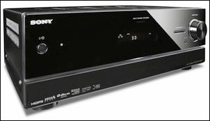 My home audio system consists mainly of "one" component, a Sony STR-DN1010 7.1-Channel A/V Receiver. The details can be seen
here.
My home audio system consists mainly of "one" component, a Sony STR-DN1010 7.1-Channel A/V Receiver. The details can be seen
here.
The info states that you can "enjoy 3D images while hearing sound closer to the way it was captured, plus improve image quality of
non-HD video sources to HD using one convenient cable. Offering plenty of connectivity options for your expanding lifestyle, this A/V
receiver features 4 HDMI inputs, 3 component inputs and is SIRIUS Satellite Radio-ready. You can also share your music in multiple
rooms with wireless 2nd zone technology".
I do enjoy its overall performance but when my "FM-quest" started, I thought (wrongfully) that the FM tuner in the STR-DN1010 would
perform OK! I was very wrong . . . but it took some time to find out.
Listening to the FM analog stereo @ 104.9 Mhz showed distortion, poor channel separation and overall "noises". At one point it
appeared that it was signal overload, so adding some attenuation should improve the overall performance. After adding 40db in line
to the 75 ohm input connector, the sound would, at times, be almost "perfect"! The reason was that it would drop stereo
reception and switch to "monaural" operation.
Then conditions would change and the received FM audio quality would again be extremely poor. Changing the attenuation to 20db,
the receiver noise would increase indicating some kind of rcvr desense. I started to realize that it basically was mass produced FM
tuner with IF selectivity problems.
To test this theory, move off the main frequency on either side of center frequency. If the IF selectivity is adequate, the channel
should go away. For example, 104.9 was changed to 104.8 but the channel was clear, now in MONO. Even at 200khz away, the channel
was still somewhat audible . . . and that shouldn't be. In other words, the FM tuner in the STR - DN1010 is crap!
There are some interesting sites that discuss the various tuner problems with references to knowledgeable sites to fix/improve the tuner's
performance. Check out "The Tuner Information Center" here. Take the time to read the complete
discussion and you'll be much more knowledgeable about FM tuners.
I'm sure that my STR-DN1010 FM tuner could use a gang filter section to improve the awful IF selectivity. That's a task for
another day.
|
Sony XDR-F1HD FM Tuner
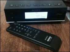 So how about a "new" tuner?? While FM tuner shopping, I read about the Sony XDR FM tuner that can receive analog AM and FM,
as well as digital AM and FM stations that have adapted HD Radio technology. So maybe I can still find one??
So how about a "new" tuner?? While FM tuner shopping, I read about the Sony XDR FM tuner that can receive analog AM and FM,
as well as digital AM and FM stations that have adapted HD Radio technology. So maybe I can still find one??
Many have abandoned AM and FM in favor of Internet and satellite radio but the sound quality doesn't compare to clean FM
signal. [I've recently made some spectrum analysis plots of KUSC FM HD1, KPBS HD1 and HD2. The
spectrum is full to beyond 15Khz, so my initial observation wasn't correct!]
However, getting a clean OTA signal can be problematic. FM is too often plagued with static, noise, and distortion and that's
where the XDR-F1HD HD Radio is so impressive. If you have a good directional yagi, it's mostly immune to those forms of
interference. The Sony tuner pulls in hard-to-receive stations better than any high-end tuner that experts have ever used.
Some audiophiles believe the XDR-F1HD may be the best tuner available, regardless of cost, and many agree.
I've always wanted a Sony XDR-F1HD tuner but today, it is hard to find. But after some searching, I found one that was in
stock condition, so I bought it. At the same time, after reading the fame of this tuner, I consulted K6STI's site
here for information on the Sony XDR tuner. He has tested it in detail
although some of it doesn't check-out with my findings. You should read the info contained there and follow the
recommendations except for the treble rolloff 'cap' mod.

 Another prominent Sony XDR tech is Dave known as "XDRguy". His site
here details the many aspects of his repair and upgrade of the Sony XDR tuner.
Another prominent Sony XDR tech is Dave known as "XDRguy". His site
here details the many aspects of his repair and upgrade of the Sony XDR tuner.
The left picture shows a completed, upgraded Sony XDR tuner with a custom audio preamp (lower noise/less loss), upgraded power supply with
new caps, two (2) added cooling fans, Memory Backup mod, FA/HD switch w/ LED and gold plated L + R output connectors. Unit is also realigned
for improved S/N ratio ensuring great reception for a low level RF input signal.
I especially like his bench setup including a Sony XDR Tuner and Sangean HDT-1X. The HP8903 Audio Analyzer and the Panasonic VP-8191A FM
Signal generator are key instruments to properly align and test a Sony XDR tuner.
XDRGuy Offers "K6JRF Audio Preamp Mods"
Received an email from Dave, XDRGuy that stated in part: "I�m revisiting some less costly ways
to improve the XDR-F1HD�s audio and save time in the process. Your work is the go-to reference so I�ve been reviewing your
data. I�m trying out a new lower-cost �Essential Mods� package, tentatively priced $120. The new package is documented on
my web page and references the K6JRF Audio Mods. We�ll see what happens. Always enjoy reading your web page. Good stuff.
"
I get emails from many who state that the cost of buying a Sony XDR-F1HD with the "pro-mods" keeps them from buying one b/c
it's just too expensive. Some time back, I mentioned that and he is now offering a resonable cost service to perform my
mods (Cap Removal, NFB and BR mods) link - here as part of his
"Essential Mods Package A".
Now YOU can buy a 'stock' Sony XDR-F1HD ($250) and send it to Dave for the mods ($120) - all at a resonable cost. I believe
many will thank him for this new service.
|
My Sony XDR Arrives . .
After unboxing it, visually inspecting it (appeared to be perfect!), I connected the 75 ohm coax as well as the L - R audio output cable to
the STR DN1010 amplifier. After setting the clock and other housekeeping task, a "SCAN" was performed.
To say that the sound quality is amazing is an huge understatement! The sound (even with its deficiencies) is absolutely amazing! And the
channel separation places you in the center of the concert hall. The sound field settings on the STR DN1010 are quite good and turn the
line-level L - R tuner output into room filling stereo sound. Needless to say I spent a lot of time listening and tuning for FM stations,
both analog and digital.
Since I've had the SonyXDR tuner, I've NEVER heard any 'noise' (background, hiss, etc) when listening to an FM HD) or analog
stereo broadcast. Well today, I did!
We had a band wipeout similar to the satellite summer and winter equinox; the signal started to drop . . . from 3 bars and
solid HD) to HD) gone away, then 2 bars, then 1 bar and finally "0" bars! At that instant, a flute passage was airing and
with it some 'noise'!
I'm sure that the DSP was having a hard time distinguishing between the flute and 'noise'. It wasn't much but there was
some!
|
This tuner has been around since 2009 and it was an instant hit back then. Click
here to read a 2009 article on the tuner.
|
|
KUSC FM @ 91.5Mhz Coverage
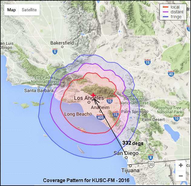
 One of the best So Cal FM stations is KUSC @ 91.5Mhz from Los Angeles. During a "SCAN", I found that it was received
at my house with typically "one" bar (out of three) indicating that I MAY be able to get a decent signal with my yagi turned
towards Los Angeles!
One of the best So Cal FM stations is KUSC @ 91.5Mhz from Los Angeles. During a "SCAN", I found that it was received
at my house with typically "one" bar (out of three) indicating that I MAY be able to get a decent signal with my yagi turned
towards Los Angeles!
Today, I beamed the antenna toward KUSC xmitter site [34 12 48 N; 118 03 44 W] to see the signal level possible.
Maybe three (3) bars is in my future??
The beam heading from my house [32 49 6 N; 117 10 27 W] to KUSC is 332 degs. The distance and heading can be
calculated from a program here. It calculates that my
house to the KUSC transmitter is 109 miles.
Looking at the chart it clearly shows, I'm in the far-fringe area. The good news is the station employs 39KW and the
antenna is at 2923 ft and finally, the Tx site is 5541 ft above sea-level!
Click here for KUSC FM transmitter data.
Radio Horizon
Radio Horizon (RH) is the total of vectors on the earth's surface where the transmitting antenna's energy are tangent to
the surface. Also the radio horizon for a fixed antenna varies with refraction by the atmosphere of radio waves.
The radio horizon extends beyond the visible horizon in conditions of normal atmospheric refraction and sometimes it is
substantially increased (or decreased) depending by propogation conditions. The distance of the radio horizon is given
approximately by the equation Rh = (17 x H)1/2 where Rh is the distance in kilometers and H is the height in meters
of the antenna above the surface.
For KUSC, their Rh = 106.2miles. For me, it's 28.1 miles. The total is 134.3 miles. Of course, this assumes no
"obstructions" in the path. Physically, the distance from their Tx and my Rx is 109miles. So it's somewhat easy to see
why their signal is 'readable' in San Diego, CA.
|
[Email from KB7NIE - tried to reply to email address but it was denied!]
 Question about your Stellar Labs Yagi setup for broadcast FM reception: Have you compared reception using vertical vs
horizontal polarization? Broadcast FM transmitters are vertically polarized, while your
receive antenna is horizontal. I didn't see mention of one versus the other in your website. Thanks! 73,Henry
Question about your Stellar Labs Yagi setup for broadcast FM reception: Have you compared reception using vertical vs
horizontal polarization? Broadcast FM transmitters are vertically polarized, while your
receive antenna is horizontal. I didn't see mention of one versus the other in your website. Thanks! 73,Henry
Not sure where you got the idea that commercial FM stations broadcast with vertical
polarization only. Certainly not b/c the tower is "vertical" does it mean that its signal is vertically polarized. Some
low power college and non-commerical FM stations broadcast with vertical only patterns but these are typically
located at colleges, such as San Diego Community College that owns/runs KSDS @ 88.3Mhz. They broadcast a vertical signal
at height of 520 ft above sea level w/ the antenna's height of 170ft.
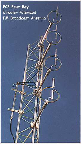
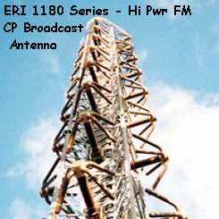 If you examine the FCC license info for commercial FM stations, you will see that they require the same (identical) ERP
for both horizontal and vertical polarizations for commercial stations. As stated above, some "college"
stations broadcast more power vertically than horizontally - to aid mobiles. [That is controversial - read the link
below] but most "large" FM stations use circular polarized [CP] antennas. They are lossy and expensive but they are
regurlarly used to satisfy the FCC license requirement for commercal stations. Shown in the left picture is from ERI; 1180
series CP FM broadcast antenna capable of 140KW power broadcasting an omnidirectional signal! In the right picture: PCP FM
Broadcast Antenna- 4 bay w/ 3dB gain broadcasting a directional signal.
If you examine the FCC license info for commercial FM stations, you will see that they require the same (identical) ERP
for both horizontal and vertical polarizations for commercial stations. As stated above, some "college"
stations broadcast more power vertically than horizontally - to aid mobiles. [That is controversial - read the link
below] but most "large" FM stations use circular polarized [CP] antennas. They are lossy and expensive but they are
regurlarly used to satisfy the FCC license requirement for commercal stations. Shown in the left picture is from ERI; 1180
series CP FM broadcast antenna capable of 140KW power broadcasting an omnidirectional signal! In the right picture: PCP FM
Broadcast Antenna- 4 bay w/ 3dB gain broadcasting a directional signal.
Click the link here to read a 'treatise' on
the use of CP vs VP. Towards the end of the article, the author states:
"Once CP is at the same ERP as VP, you should have some improved reception to vehicles that may be experiencing multi-path
distortion. In urban areas with an increased possibility of reflections, you may notice CP has less momentary signal
fluctuations as you drive through these reflections. They are typically very brief, lasting a fraction of a second and
do not cause the listener to change channels. In these cases CP may provide a signal that is a bit more consistent but not
with increased range or distance."
So the author concludes that CP actually performs better than VP independent of all REQUIREMENTS (FCC, legal, etc).
CP, despite its high cost, actually provides a better signal to all users including those in vehicles.
|
 The left side picture shows that the orientation of the SL 4el yagi is NOT 335 degs!! The reason is obvious when you look at
the pattern. It's tuned for XLNC @ 104.9Mhz, so its F/G and F/B ratio @ 91.5Mhz is "awful"! The F/G is 4.8db and F/B = 8db
so it has more gain off the back side than the front! So when re-designed for KUSC @ 91.5Mhz, it should give me reliable year
round reception. See the yagi section below for the KUSC results.
The left side picture shows that the orientation of the SL 4el yagi is NOT 335 degs!! The reason is obvious when you look at
the pattern. It's tuned for XLNC @ 104.9Mhz, so its F/G and F/B ratio @ 91.5Mhz is "awful"! The F/G is 4.8db and F/B = 8db
so it has more gain off the back side than the front! So when re-designed for KUSC @ 91.5Mhz, it should give me reliable year
round reception. See the yagi section below for the KUSC results.
Wow ... three bars and the HD)) symbol!
[Unfortunately the HD) blinks/goes off and
the 3 bar level becomes as low as 1 bar!]
As an aside, the received FM audio produced by the Sony XDR tuner is outstanding after the ckt mods (described below) are made. There
are differences in audio quality the three (3) FM stations.
Ranking the three (3) stations . . .
KUSC - - - #1 by a small margin using HD1 - no compression*, great clarity and high presence!
KPBS - - - #2 almost equal to #1 using HD2 - lower presence and some compression* due to HD2 bw restrictions.
XLNC - - - #3 lowest of the three; only analog monaural FM. High THD at times and low S/N ratio; can hear noise about
-50db down **
* = obviously, some recordings MUST be compressed.
** = Mar 1, 2018, they will cease FM OTA broadcasting and use Internet only.
|
Sony Tuner Heat Problems
 After using the tuner all evening, the case temperature is a bit alarming! It measured 128F. Resting your hand on top was a bit
uncomfortable. The picture shows the detailed temperature measurements made with an infrared sensor. As many know, extended temperature
will shorten the life of the components, esp the capacitors even though the PS Board uses 65C hi-temp capacitors. The internal
temperature is higher than I would like it to be so something has to been done.
After using the tuner all evening, the case temperature is a bit alarming! It measured 128F. Resting your hand on top was a bit
uncomfortable. The picture shows the detailed temperature measurements made with an infrared sensor. As many know, extended temperature
will shorten the life of the components, esp the capacitors even though the PS Board uses 65C hi-temp capacitors. The internal
temperature is higher than I would like it to be so something has to been done.
The 10.5 volt produced on the PS Board, is half-wave rectified. Some have added another
diode to make it a full-wave rectified voltage. Adding the diode will slightly RAISE the internal temperature b/c of the higher
average current value of the rectified voltage produced by the added rectifier. It's not needed since the 10.5V is again "regulated"
to 8.5V (in IC902) with added filtering provided by R302, C302 (LPF to the Audio Preamp ckt) and C10 (to the DSP Tuner Unit).
|
Cooling Fan Added
 I removed the cover and added a fan as shown in the picture. I usually use a glue-gun but this time I used a double-sided tape
strip since the fan's weight is not a problem for the tape's adhesive strength. To ensure that it won't droop due the high temperature
in the case, I added two (2) support posts super-glued on each side of the fan. They are visible as "white-spots" in the
picture and rest on top of each capacitor under the fan.
I removed the cover and added a fan as shown in the picture. I usually use a glue-gun but this time I used a double-sided tape
strip since the fan's weight is not a problem for the tape's adhesive strength. To ensure that it won't droop due the high temperature
in the case, I added two (2) support posts super-glued on each side of the fan. They are visible as "white-spots" in the
picture and rest on top of each capacitor under the fan.
My rationale for the site chosen is that it appears to be optimum b/c hot air is drawn from the transformer, power supply
components from the bottom of the case and then forced out the back. The fan is an "Evercool", 12Vdc fan with apx 1W power
draw.
I soldered it to the 5.2V tap so it would run at low speed and be noiseless. When the XDR tuner is
"OFF" the voltage rises to 6.8 V and moves even more hot air from the inside. Did not "gate" it with a control signal b/c
it should run continuously to cool the cabinet even when the main power is "OFF". When measured after sitting for 8 hours, the top
cabinet temperature was 78F with the room temp at 75F. Since it can't be heard, why not take advantage of as much cooling as possible.
 This fan placement is not without a consequence; the case inside "lip" must be cut as shown in the picture and the center
post must be removed. This is not a problem since the four screws adequately/securely hold the case together.
This fan placement is not without a consequence; the case inside "lip" must be cut as shown in the picture and the center
post must be removed. This is not a problem since the four screws adequately/securely hold the case together.
In order to raise the unit and not make it look too obvious, I added felt pads, apx 3/16" thick to raise the bottom above
the cabinet top so that there is less restriction on input air flow.
|
Heat Mods Results
 With the cover installed and running, the picture shows the measured temperatures on a 90F outside temp day. Inside the temp was 79F
with the cabinet top at 83.4F. This is mainly due to the STR DN1010 amplifier power dissipation as heat BION.
With the cover installed and running, the picture shows the measured temperatures on a 90F outside temp day. Inside the temp was 79F
with the cabinet top at 83.4F. This is mainly due to the STR DN1010 amplifier power dissipation as heat BION.
The XDR cabinet top was reduced to 101.5 F, a decrease of apx 25+F degs. The air exit temp is 99.5F showing that the fan IS doing
its job. All things considered, a worthwhile and necessary modification.
The weather has cooled (66F outside) and the SonyXDR tuner has a new home (on a shelf), so I took temperature measurements to see what it
is now with a 70F house temperature. Very nice!
|
Memory Backup Mod
As fine as the unit is, there is no memory backup ckts in the Sony XDR tuner, BION. You'd think that it would have been a major design
function. But it wasn't. So the user looses all stored parameters (clock, LCD display and all memory presets) are wiped clean when main
power (120Vac) is lost. Another serious deficiency that must be fixed.
 There are two (2) main ways to provide memory backup; use a "large" cap such as a 1.5 Farad or a battery. Of the two, I prefer the
battery method since it can potentially last at least 2-3 years or more! So I chose the battery method.
There are two (2) main ways to provide memory backup; use a "large" cap such as a 1.5 Farad or a battery. Of the two, I prefer the
battery method since it can potentially last at least 2-3 years or more! So I chose the battery method.
I have a LIR 2450 3.6V LiOn button battery with leads, so it's the natural choice. Also using the battery method, you don't
have to remove the main PCB, all mods can be made from the top side.
The LIR 2450 specs are here. Max current draw is 120ma so there's a lot of headroom.
In charging the battery, you need to limit the charge voltage to 4.2V max. Charging from a 4.7V ckt, could present problems for the
battery over a long time.
After making measurements with the Sony tuner operating, the voltage can NOT exceed 4.2V b/c of the D912 forward voltage drop.
But the voltage comes very close, so I studied the ckt awhile and the fix was obvious.
Resistor Method
The measured D912 forward voltage drop is only 0.6V (4.7 - 4.1 = 0.6V) so that means there is very little current flowing
through it. The solution is obvious . . cause more current flow through D912 in order to raise the FV drop to 0.7V or 0.8V
by adding a resistor to ground. That will lower the max charging voltage to 4.1V. Perfect!
 Rephrasing the above; currently, the FV drop through D912 is apx 0.6V making the terminal charging voltage of 4.1V. Adding the
resistor (Rbc = 27K) causes the FV drop to increase to 0.74 reducing the terminal charge voltage to 4.0V. You can
increase Rbc value but more current is 'wasted' (in the OFF state, the battery must supply this current) further lowering the
available charging voltage.
Rephrasing the above; currently, the FV drop through D912 is apx 0.6V making the terminal charging voltage of 4.1V. Adding the
resistor (Rbc = 27K) causes the FV drop to increase to 0.74 reducing the terminal charge voltage to 4.0V. You can
increase Rbc value but more current is 'wasted' (in the OFF state, the battery must supply this current) further lowering the
available charging voltage.
Note that D914 is not effected b/c the current flow to the Memory is low (90ua) so it's FV drop is still 0.6V.
The right side chart shows what happens by using a Spice transient analysis where the 4.7V regulator is turned on for 20sec and
then off for 60sec to 100sec total. The analysis shows the battery at 4.0V which is close to the max voltage point, 4.02V before
draining some charge forcing the battery to recharge.
Using Spice, a resistor of apx 27K ohms will cause enough extra current to flow that raises the D912 FV drop to 0.74
volts. The added resistor (Rbc) does the job and ensures that there will never be excess voltage applied to the Li-ion
backup battery.
 What happens is this; as the battery slowly charges, it reaches a point where the battery's charge voltage
equals the available charging voltage. At that point the ckt reaches equilibrium; ie, the battery charging current is
"zero". So now the battery will start to slowly discharge. As that happens, the battery voltage drops to a point where now it
can be charged. The equilibrium point is apx 4.025 Volts of battery charge voltage.
What happens is this; as the battery slowly charges, it reaches a point where the battery's charge voltage
equals the available charging voltage. At that point the ckt reaches equilibrium; ie, the battery charging current is
"zero". So now the battery will start to slowly discharge. As that happens, the battery voltage drops to a point where now it
can be charged. The equilibrium point is apx 4.025 Volts of battery charge voltage.
The chart on the right shows the a plot of Li-ion battery (B1) voltage plotted against the charging current (TPi2). At 4.02V, the
charging current is barely positive (10ua). At 4.03V, the battery charging current is negative meaning that the battery is reached
its max terminal voltage and is now discharging. Thus the battery can't charge above 4.02V. Neat solution IMO.
 Without the 27k Rbc resistor, my measurements showed 4.19V @ D912 cathode, tuner ON. With the tuner OFF, this results
in apx 35ua current draw with battery = 4.17V. At that current discharge rate it will provide memory backup for a very
long time! With the Rbc (27K) resistor added, the values change as shown in the above Spice chart.
Without the 27k Rbc resistor, my measurements showed 4.19V @ D912 cathode, tuner ON. With the tuner OFF, this results
in apx 35ua current draw with battery = 4.17V. At that current discharge rate it will provide memory backup for a very
long time! With the Rbc (27K) resistor added, the values change as shown in the above Spice chart.
The picture shows the details with the cooling fan removed for clarity. Solder at the points shown; JW20 for "ground" and D912 cathode for
the 220 ohm resistor going to the LIR 2450 "+" side. The Rbc resistor is soldered to the junction of D912 cathode as shown. This is a very
simple and straightforward method which I believe is the best method. So far, I've tested the backup system for three (3)
months with no memory loss. Even the clock time setting is preserved.
Zener Diode Method
Another way to accomplish the 4.0V "clamp" action on the Li-ion battery is to use a zener diode. With todays technology,
almost all voltage variations are available. One such zener from NXP Semiconductors is their 4.1V zener with 2% tolerance.
With that tight tolerance, it's possible to use it b/c UPPER limit = 4.11V, the LOWER = 4.02V. Mouser PN: 771-NZX4V3A-133.
Perfect for this application.
 There isn't a Spice model for the NXP zener diode so I used a 3.9V, 5% zener's characteristics to get the same UPPPER voltage limit of
"4.1V". Using that zener in the Spice analysis shows the Li-ion battery at 4.08V, just before zener action at 4.1V. Inspection shows
the same action as in the "resistor" version except there is more current flow b/c of the low zener impedance of 100 ohms.
There isn't a Spice model for the NXP zener diode so I used a 3.9V, 5% zener's characteristics to get the same UPPPER voltage limit of
"4.1V". Using that zener in the Spice analysis shows the Li-ion battery at 4.08V, just before zener action at 4.1V. Inspection shows
the same action as in the "resistor" version except there is more current flow b/c of the low zener impedance of 100 ohms.
During my tests, the Li-ion battery started at 4.17V at the time that the zener was installed. The battery steadily discharged at apx 35ma
as the terminal voltage steadily decreased to 4.08V. This zener has a 100 ohm zener impedance which is consistent with the
observed current flow.
So this concept works nicely but it's a bit "tougher" on the battery. Also not EVERY zener has the desirable characteristics of the NXP
zener. However, this shows the versatility that can be employed in arriving at a solution.
|
|
Analog Forced Reception Mod
 Today was a good example of the need for Forced Analog [FA] reception. As the weather got bad and started to rain, reception
from KUSC @ 91.5Mhz degraded so that the HD) icon was stable for 2 minutes, then would start to flash. When that happens the
Sony XDR tuner switches from digital to analog and there are definitely artifacts while switching back and forth!
Today was a good example of the need for Forced Analog [FA] reception. As the weather got bad and started to rain, reception
from KUSC @ 91.5Mhz degraded so that the HD) icon was stable for 2 minutes, then would start to flash. When that happens the
Sony XDR tuner switches from digital to analog and there are definitely artifacts while switching back and forth!
Pic by Bob Meister, WA1MIK
To say it's not pleasant listening is an understatement. So time for the FA Mod. Many have written about it and perform
the required PWB cut, switch addition and wiring interconnection. If you are not proficient at making cuts to 5mil
traces that are 2mils apart, then maybe somebody who is should do it for you.
 I've indicated where I made the cut to the PWB b/c it's closest to pin 23 and the easiest spot to make a cut w/o having an
"accident" and cutting some adjacent trace.
I've indicated where I made the cut to the PWB b/c it's closest to pin 23 and the easiest spot to make a cut w/o having an
"accident" and cutting some adjacent trace.
Solder two wires as shown and bring them up to the top side of the main board by snaking them up one of the many holes
on the board. I drilled a 1/4" hole on the back panel as shown in the picture to mount the switch. It is orientated
up for "HD" and down for "FA".
If you have a DPDT switch, then some have added a blue LED so that the user can see if it's in the FA (or HD mode, your
choice) mode. That's all there is to it!
|
Treble Audio Rolloff Discussion
 Testing has reported that the Sony XDR FM Tuner experiences treble rolloff from the PreAmp Ckt and is anywhere from -1.5 to
-2.5dB @ 15Khz. The chart shows a typical test of a Sony XDR tuner showing -2.3dB loss at 15Khz.
Testing has reported that the Sony XDR FM Tuner experiences treble rolloff from the PreAmp Ckt and is anywhere from -1.5 to
-2.5dB @ 15Khz. The chart shows a typical test of a Sony XDR tuner showing -2.3dB loss at 15Khz.
Every Sony tuner is somewhat different but measurements show that they all seem to fall into this defined attenuation range. Before
actually digging into this problem, I simply removed the four (4) caps no matter what treble loss they contributed. In hindsight,
I'm not sure I heard that amount of treble rolloff on my Sony tuner. Tuners with circuit failures certainly would exhibit more
treble rolloff than a 'good' one.
I employed a K6STI chart that showed the treble rolloff of his Sony XDR tuner of -2.3dB @ 15Khz. After receiving a
email from him, I decided to use my own charts. Up to this time, I hadn't really "checked" my Sony tuner for its
loss . . . just assumed that mine would be the same or less. I did NOT verify the results myself. There's a
lesson here, don't you think??
5Spice preamp ckt simulation showed -0.56db @ 15Khz and -0.89db @ 20Khz. Since Spice is never wrong
*, the remaining rolloff is due to the DSP Tuner module. In other words,
the Preamp contributes -0.6dB @ 15Khz and the DSP Tuner + preamp totals to -2.2db rolloff.
 XDRguy's site shows a "Pete Millett" unmodified Sony XDR rolloff measurement. The sweep results of the PreAmp ckt
show -1.5dB @ 15Khz attenuation. So there are some differences evident and we still are
not certain "why" there are differences. He also has reported 0.5dB rolloff variations @ 15Khz with different Sony XDR tuners
that he has tested.
XDRguy's site shows a "Pete Millett" unmodified Sony XDR rolloff measurement. The sweep results of the PreAmp ckt
show -1.5dB @ 15Khz attenuation. So there are some differences evident and we still are
not certain "why" there are differences. He also has reported 0.5dB rolloff variations @ 15Khz with different Sony XDR tuners
that he has tested.
XDRguy measurement of the Sony XDR Treble Rolloff [from "RF In" to "L+R output"] shows -2.3dB loss @ 15Khz and
claims that it's from the PreAmp ckt, not the DSP Tuner module portion of the Sony XDR. The chart at the beginning of this section
is taken from that data. However, I believe that the loss is not all from the Preamp ckt itself.
* Certainly the results are only as good as the model. If it's incomplete, so are the results! When the correct transistor
model [see the THD Analysis section below] was located and incorporated into the simulations, the results dramtically changed.
Now DC bias levels, THD and input drive levels to produces clipping could be accurately determined. Also, I suspected that the
characterization of DSP Tuner's output impedance wasn't correct. After some simulations, the correct value was found and has been
used in ALL simulations. The simulation results now shadow [see the Frequency Response [FR] & Total Harmonic
Distortion [THD] section below] real world performance.
What's causing the difference
So what is causing the difference?? Doing many Spice simulations, I found that 3300pf causes greater than 2dB loss @ 15Khz.
The Sony XDR ckt board is two sided with traces on the bottom side and "wire-jumpers" used to connect crossover points. They
can add 3-4pf / jumper if the trace connection is over "ground". But it would take a lot of jumpers to make
3300pf! Not a feasible answer to the problem.
Another idea was a "missing" component (a component that is on the board but doesn't appear in the PDF schematic) but none
was found.
Another explanation was the values of C12 and C22 are larger than stated. One clue to this idea, is
that removing C12 and C22, the attenuation drops to fractions of a "db". If that is true,
that would throw out two arguments; it could be layout sensitive and there's a "hidden" component. However, the theory was
not supported when measurements of the removed caps, C21, C22, C11 and C21 show values close to nominal.
One final argument concerns the output impedance of the DSP Tuner Unit. Finding the impedance that delivers half-power into
the PreAmp ckt (as the DSP Tuner's "load") will give the required value for the source resistance (Rs) used in Spice simulations.
Since the DSP Tuner is DC biased (1.7V) at output pin 27 for LEFT channel, a DC blocking cap (C19 = 1uf) and series resistance (R9
= 470) is required to prevent short-circuit failures in the DSP Tuner IC.
Using Spice, the output impedance [Z] shows to be apx 1200 ohms. And this value gives a good fit to measured results,
so all schematics have been modified to use this value. All Spice simulations were re-run. This new value has changed some of the
component values required for "Treble Rolloff - 2nd Method" and "K6JRF PreAmp Ckt Mod - 3rd Method". In
general, all steady state AC frequency measurements have changed along with the recommended cap values. This relatively
high impedance plus the four caps [C11, C21, C12, C22] contribute to the rolloff at higher frequencies.
 The latest 5Spice analysis shows different results, more in line with bench measurements. In order to be complete, I've
added the MUTE ckt into the schematic so that the "total" ckt can be analyzed.
The latest 5Spice analysis shows different results, more in line with bench measurements. In order to be complete, I've
added the MUTE ckt into the schematic so that the "total" ckt can be analyzed.
XDRguy asked about R302 (47) and C302 (470uf) ckt components. The R-C ckt forms a low pass filter which
decouples the 8.5V power-line from other ckts using this voltage. The attenuation at 10Khz is apx -100dB!
This RC ckt feeds power to the PreAmp LEFT and RIGHT channel so the power consumed in the opposite channel (RIGHT) must be
included. The Rrchn resistor represents the DC current drawn by the RIGHT channel preamp, apx
3.25ma. In previous analysis I hadn't included both the LPF and Rrchn. Since both effect the operating DC BIAS
for the LEFT channel, these ckt components s/b included. Tnx Dave! The new DC bias values are shown in blue next to the ckt
node. Note that there's no change to the "AC" steady state analysis.
Results show -2.14dB @ 15Khz with nominal values for all circuit components.
So, in summary, the observed PreAmp ckt treble loss has variation from different authors ranging from
-1.5dB to -2.5db. Until I actually make some measurements myself, I still believe that the DSP Tuner
Module plus the PreAmp ckt cause the observed attenuation at 15Khz but, to date, measurements by others don't confirm the idea. But,
bottom line, we now have a realistic circuit simulation model for an unmodified Sony XDR FM Tuner's PreAmp Ckt.
Total Harmonic Distortion [THD] Analysis
I stated earlier that you shouldn't expect to measure excessive THD from three (3) caps, two (2) transistors and a few resistors!
So I decided to see what 5Spice says about the LEFT channel of the SonyXDR Preamp ckt.
5/8/16: Spice model for 2SC3052 transistor employed to update results.
The original analysis used a "2N3904" NPN AF transistor for Q102 and Q103. After finding a correct
model
[2SC3052] for those critical transistors, ALL ANALYSIS were repeated and, as expected, some results changed!
 The 5Spice analysis shows that I was partially correct! At low signal levels (0.25Vpk), the preamp's THD performance is quite good but
due to the limited operating headroom, THD rises with higher signal levels. The results are shown in the chart.
The 5Spice analysis shows that I was partially correct! At low signal levels (0.25Vpk), the preamp's THD performance is quite good but
due to the limited operating headroom, THD rises with higher signal levels. The results are shown in the chart.
The "stock" preamp has a Low Pass Filter [R/C network R101 + C12 and R6 + C22] that is intended to attenuate high-frequency 'buzz' beyond
20Khz. It also begins to rolloff starting at 5Khz so this action lowers the THD but also causes excessive treble rolloff as you saw
previously.
To 'tame' the LPF network, remove the two (2) capacitors (LEFT channel) and that reverses the treble rolloff. The THD results is shown
under the "Mod %" column. The THD is basically unchanged with or without the 4 caps although there
is a general rise at higher frequencies.
At higher signal input level, 0.75Vpk, the THD rises as shown under the "Mod %" column. This
is due to the limited overhead operating range. Voltage values are noted in the schematic. Higher input signals forces the ckt to
approach the voltage "rail" so THD will rise. The operating DC bias numbers in blue are shown in the
schematic.
 I thought that lowered THD is still possible by making a few ckt changes. However, after doing a visual inspection, it is not that easy
to change ckt values on a SMD manufactured board. Certainly it can be done but after some Spice analysis, the lowered THD that would
result isn't that significant.
I thought that lowered THD is still possible by making a few ckt changes. However, after doing a visual inspection, it is not that easy
to change ckt values on a SMD manufactured board. Certainly it can be done but after some Spice analysis, the lowered THD that would
result isn't that significant.
However, adding Negative FeedBack (NFB) to this ckt dramatically lowers THD by forcing the ckt to operate in its
linear range at the expense of lowered preamp gain. This is a small price for such a large performance improvement. Contrary to Yahoo
forums "technical" experts, NFB for this ckt, does NOT add phase/time delay, it just lowers THD*
And that only takes one (1) added resistor per channel!
The schematic shows the NFB resistor as Rnfb = 39K as this is the "middle" of the acceptable range of values. The
NFB resistor reduces the internal preamp's THD by forcing it to operate in its limited linear range. Looking at the THD chart above in the
"NFB" column clearly shows lowered THD, as low as 0.011% @ 0.25Vpk signal level.
 Note that low frequency Bass Rolloff [BR] occurs when NFB is added. It's due to the extremely low value of C19, 1uf and
must be increased to correct the BR. The added cap is "Clfb" and can be soldered to TU1 DSP Tuner module, pin (27) and then to the
wire jumper JW14 on the underside of the Main Board (LEFT channel). Details in the "Installation" section below.
Note that low frequency Bass Rolloff [BR] occurs when NFB is added. It's due to the extremely low value of C19, 1uf and
must be increased to correct the BR. The added cap is "Clfb" and can be soldered to TU1 DSP Tuner module, pin (27) and then to the
wire jumper JW14 on the underside of the Main Board (LEFT channel). Details in the "Installation" section below.
The BR is -0.7dB with NFB resistor, Rnfb = 20K.
* It does that by reducing ckt gain ensuring that the ckt operates in its most LINEAR range.
These forums are packed with self-named "technical" experts that don't know the difference between a "hairpin" (no, it's not a
woman's hair product!) and a "decibel". Their experience is to BUY tuners, listen and get together to "judge" the better/best
tuner. Note that they haven't actually MEASURED THD so everything is strictly qualitative! This process relies on the ears
and the quality of the hifi gear. With different venues, equipment and "ears", the results are tainted!
However, this process can be fine if they realize their lack of quantitative analysis. Sadly, they don't and make statements
that some FM tuners with medium to high THD levels sound better than a low THD tuner. This is simply ridiculous. An FM Tuner is
ALWAYS designed for low THD as is possible within the ckt's constraints. It is LOW THD that makes a FM tuner become an
audiophile treasure. For the non-technical, this is the ability to reproduce a "note" exactly as it was played w/o coloration!
NFB was employed in the SonyXDR Tuner to lower THD and made it produce extremely clean (low THD and ZERO time delay) audio
as detailed in the following sections.
|
Want Lowest THD . . .
 For me, I want the absolute lowest THD possible with the SonyXDR preamp. To that end, making the NFB resistor,
Rnfb = 20K gives the lowest THD even for input signals (from the TU1 DSP unit) greater than 1.0Vpk. In fact the
preamp won't clip with the DSP Tuner's output level = 1.5Vpk! The chart shows the response at various signal levels.
For me, I want the absolute lowest THD possible with the SonyXDR preamp. To that end, making the NFB resistor,
Rnfb = 20K gives the lowest THD even for input signals (from the TU1 DSP unit) greater than 1.0Vpk. In fact the
preamp won't clip with the DSP Tuner's output level = 1.5Vpk! The chart shows the response at various signal levels.
Note the THD @ 0.25Vpk is under 0.01%, 0.04% at 0.75Vpk and 0.05% at 1.0Vpk. These are excellent numbers for basically
a one transistor amplifier (2SC3052) followed by an emitter follower (2SC3052) output with both operating on limited, single voltage
rail!
THD in "dB" . . .
 Express THD in different units, "dB".
THD is normally expressed in percent but technical people get a greater "feel" when THD is expressed in "db".
THD is defined as the ratio of the rms voltage of the harmonics to that of the fundamental component. This is measured by using a
spectrum analyzer to obtain the level of each harmonic and performing an rms summation. The level is divided by the fundamental level
and stated as the total harmonic distortion expressed in percent.
The distortion of an audio device indicates the extent to which a sinusoidal test tone signal is modified by non-linear
distortions of unwanted overtones and harmonics. It is therefore a measure of the resultant harmonic distortion.
At the "low" level of 0.05% THD, the db equivalent is -66db. That means the
distortion level is more than 2000 times down from the fundamental! So if the room's sound pressure level is 10W, the
distortion level is 5 milliwatts!
At a "higher" level of 0.5% THD, it's at -46dB. The distortion product is more
than 200 times down from the fundamental. For the 10W example, the distortion is 50 milliwatts!
Do you honestly think that you can hear these distortion products??
|
 Note that the overall preamp gain is reduced when NFB is employed. The stock preamp has 1.84x gain input to output.
Adding NFB (68K) lowers the overall gain to 1.46x. For the SonyXDR preamp w/ Rnfb = 20K, the gain is 1x. For my audio
system, the gain loss makes the other equipment's output balance out perfectly and I have a lot of "headroom" in the Sony power amplifier!
Note that the overall preamp gain is reduced when NFB is employed. The stock preamp has 1.84x gain input to output.
Adding NFB (68K) lowers the overall gain to 1.46x. For the SonyXDR preamp w/ Rnfb = 20K, the gain is 1x. For my audio
system, the gain loss makes the other equipment's output balance out perfectly and I have a lot of "headroom" in the Sony power amplifier!
Employing NFB, Spice says that there is -0.7dB @ 20hz Bass Rolloff [BR]. It is inversely proportional to the value
of the NFB resistor; 68K = -0.3dB; 20K = -0.7dB. When NFB is used, it requires the addition of cap, Clfb = 10uf in
parallel with C19 = 1uf. This removes the bass rolloff and flattens the response to -0.05db @ 20hz.
 Note that with 1.5Vpk drive signal without NFB, it is clipped on the negative rail, THD = 12.1%. With NFB, the output is
clean w/ THD = 0.038%. Not too shabby! With the 20K NFB resistor installed, your SonyXDR tuner's preamp WILL NEVER
CLIP on the strongest INPUT signal and will recover audio that has the range of 0.0x% THD [lowered by -40 [min] to over -60dB]
to boot! Note also no delay time [zero crossing point is identical] or phase shift effects added with NFB.
Note that with 1.5Vpk drive signal without NFB, it is clipped on the negative rail, THD = 12.1%. With NFB, the output is
clean w/ THD = 0.038%. Not too shabby! With the 20K NFB resistor installed, your SonyXDR tuner's preamp WILL NEVER
CLIP on the strongest INPUT signal and will recover audio that has the range of 0.0x% THD [lowered by -40 [min] to over -60dB]
to boot! Note also no delay time [zero crossing point is identical] or phase shift effects added with NFB.
|
 The chart shows the expected levels of THD vs the selected NFB resistor with range between 68K and 20K. In general, the
lower the resistor value, the lower the resultant THD. The reason is simple; the lower resistor value reduces the preamp's gain from
apx 1.9x with-out NFB to 1.0x with 20K. The use of a 20K NFB resistor guarantees that the preamp will not clip and, at the same time,
will produce the lowest THD possible for the preamp. It is the natural choice.
The chart shows the expected levels of THD vs the selected NFB resistor with range between 68K and 20K. In general, the
lower the resistor value, the lower the resultant THD. The reason is simple; the lower resistor value reduces the preamp's gain from
apx 1.9x with-out NFB to 1.0x with 20K. The use of a 20K NFB resistor guarantees that the preamp will not clip and, at the same time,
will produce the lowest THD possible for the preamp. It is the natural choice.
If you compare the preamp gain vs NFB resistor values shown in the chart, it is a no-brainer that NFB is the way to go. The onset of
clipping for the SonyXDR internal preamp is just above 1.0Vpk input. The THD is over one order of magnitude higher w/o
NFB. This is probably why the SonyXDR FM Tuner's performance without NFB makes it sound "dull".
The tradeoff for this THD improvement is a loss of gain through the preamp, a small price to pay for the lowered distortion level. It's an
understatement to say that NFB has improved the quality of my preamp's audio output!
|
NFB Resistor + BR Caps Installation . . .
 I recommend that you use a resistor similar to this one at Mouser
20K, 1/8W film
resistor and solder between the junction of R110 and C101 on the "input" side. And between C102 and R109 on the "output" side for the
LEFT channel. For the RIGHT channel, between R210 and C201 on the "input" side; between C202 and R209 on the "output" side as the picture
shows. Suggest that you use shrink sleeving so it can't short on the many other parts in that area.
I recommend that you use a resistor similar to this one at Mouser
20K, 1/8W film
resistor and solder between the junction of R110 and C101 on the "input" side. And between C102 and R109 on the "output" side for the
LEFT channel. For the RIGHT channel, between R210 and C201 on the "input" side; between C202 and R209 on the "output" side as the picture
shows. Suggest that you use shrink sleeving so it can't short on the many other parts in that area.
When complete, you can check with an ohmmeter; since the two 20k resistors are isolated, a resistance measurement should read 20k ohms. If
it reads other, then you have soldered the NFB resistor on the wrong side of the R and C combination.
Be careful on the amount of "heat" (650-700 deg F iron) that is applied to the junction being soldered. I use a small flat blade
screwdriver to hold the wire to the part after the joint has been 'fluxed'. Too much heat and the SMD cap or resistor will be moved or,
worse, slide off.
|
 The addition of 10uf cap is somewhat problematic. The BEST solution is to use a small, low voltage axial tantalum cap. These are
small enough so they can be soldered to the underside of the Main Board [MB] and still be able to mount the MB on the posts.
The addition of 10uf cap is somewhat problematic. The BEST solution is to use a small, low voltage axial tantalum cap. These are
small enough so they can be soldered to the underside of the Main Board [MB] and still be able to mount the MB on the posts.
The tantalum caps
10uf, 6V solid tantalum capacitor arrived from Mouser. They are 2.8mm (0.1") diameter and 7.8mm (0.3") long.
The picture shows the convenient way to mount the small tantalum caps; the LEFT cap is soldered to pin 27; the RIGHT to pin 26. The negative
leads solder conveniently to JW14 and JW15 respectively.
|
 If you prefer using a 'standard' aluminum cap, the picture shows how to do this. The 10uf, 16V radial caps and mounted on the top side and
the holes in the MB allow "ONE" lead (+) to extend to the MB bottom side. It's soldered on the appropriate pin of TU1 module, DSP Tuner
Unit.
If you prefer using a 'standard' aluminum cap, the picture shows how to do this. The 10uf, 16V radial caps and mounted on the top side and
the holes in the MB allow "ONE" lead (+) to extend to the MB bottom side. It's soldered on the appropriate pin of TU1 module, DSP Tuner
Unit.
For the LEFT channel - Pin 27; for the RIGHT channel - Pin 26. The LEFT cap's negative lead solders to JW14; RIGHT cap's
negative solders to JW15.
|
Frequency Response [FR] & Total Harmonic Distortion [THD] Measurement
 This was the first set of measurements made by Dave, XDRguy * using my mods on a
SonyXDR-F1HD. As he is interested in improving his external preamp, so am I for the SonyXDR's internal preamp.
This was the first set of measurements made by Dave, XDRguy * using my mods on a
SonyXDR-F1HD. As he is interested in improving his external preamp, so am I for the SonyXDR's internal preamp.
He modified a stock SonyXDR that he was preparing for sale, so he could make FR and THD measurements with his labratory grade
equipment.
For the THD measurements, he modified a stock SonyXDR by removing four (4) caps [C11-12, C21-22] and adding a 68K NFB
resistor. Results show apx 0.05% THD across the frequency band from 20hz to 30Khz under low signal level. THD is flat
until a slight rise at 29Khz = 0.07%. Impressive indeed!
 However, with lower NFB resistor values, the THD can be further reduced!
To that end, Dave modified another stock Sony XDR to include the NFB resistor = 33K ohms and Clfb=10uf. Then
ran a FR and THD analysis producing the following two (2) charts.
The FR chart shows the results of the Sony XDR with K6JRF mods. The FR is flat from 20hz to 20Khz +/- 0.12dB. The
chart shows the THD for two (2) values of NFB resistor and a 5Spice data from a Distortion Analysis.
 For the THD measurements, the AQUA colored curve shows the actual measured THD for the
modified Sony XDR with NFB = 33K ohms. The BLUE curve shows the projected THD+N with
the recommended NFB resistor = 20K ohms. This curve shows THD less than 0.07% from 40hz to 28.1Kz.
For the THD measurements, the AQUA colored curve shows the actual measured THD for the
modified Sony XDR with NFB = 33K ohms. The BLUE curve shows the projected THD+N with
the recommended NFB resistor = 20K ohms. This curve shows THD less than 0.07% from 40hz to 28.1Kz.
The data shown in the RED curve shows the Spice THD analysis with drive signal, Vin = 0.75Vpk. The THD
is less than 0.04% from 20hz to 20Khz.
The THD curve in RED follows the shape of the other charts except for frequencies below 60hz. THD analysis
of this kind require a circuit settle-time due to ckt R-C time constants. Measurements performed as in a 'transient' analysis will show
much higher THD numbers than are actually there when the THD measurement is made if the ckt has NOT been allowed to settle. Differences of
an order of magnitude [0.25 vs 0.02] are commmon. I suspect that the THD measurements didn't settle so that accounts for measured
differences. All three (3) curves show good correlation except as noted.
* XDRguy made the above measurements and I'm pleased with the results. For those who have been following my Sony XDR
mods, they are made from 40+ years of electronics design experience and verified with Spice simulations. However, I don't have the
test equipment to make FR and THD measurements. Dave's work, on the other hand, is anchored in testing and measurement. Again tnx for
quantifying my XDR modifications.
Spectrum Analysis
 When the FCC approved the transmission of stereophonic sound, it had to be compatible with FM mono rcvrs. To do this, the 0 to 15Khz
base band part of the multiplex (MPX) signal had to contain the left (L) and right (R) channel information (L+R) for monophonic
reception.
When the FCC approved the transmission of stereophonic sound, it had to be compatible with FM mono rcvrs. To do this, the 0 to 15Khz
base band part of the multiplex (MPX) signal had to contain the left (L) and right (R) channel information (L+R) for monophonic
reception.
Stereophonic sound is achieved by amplitude modulating the (L-R) information onto a suppressed 38Khz subcarrier in the 23 to 53Khz
region of the base band spectrum. A 19Khz pilot tone is added to the multiplex signal to enable FM stereo receivers to detect and decode
the stereo left and right channels. The composite base band signal format meets the backwards compatibility needed for FM mono receivers
while simultaneously providing enough information for FM stereo receivers to decode the left and right stereo channel outputs. Today�s
MPX signal includes a 57Khz subcarrier that carries RDS and RBDS signals.
 Using my modified Sony XDR, a spectrum analysis showing KUSC and KPBS made on 12/11/16. Object was to see how much actual BW is
employed by the more popular FM radio stations. Was surprised to see the KPBS_HD3 employs only 8.9Khz of operating bw.
Using my modified Sony XDR, a spectrum analysis showing KUSC and KPBS made on 12/11/16. Object was to see how much actual BW is
employed by the more popular FM radio stations. Was surprised to see the KPBS_HD3 employs only 8.9Khz of operating bw.
In contrast, the KUSC_HD1 spectral data was taken from a live broadcast of the LA Phil with the LA Master Choral group. Note that
16.1Khz of operating bw was measured. Also note the large amount of "rumble" shown in the 20hz to 40hz area. For contrast, a plot
of white noise is shown to be very flat across the 20hz to 20Khz frequency spectrum showing that the audio recorder/player produced an
accurate spectral analysis chart.
Data was captured by use of Spectra Plus-SC program. Details here
|
External Preamp
Using a modern day opamp to replace the discrete transistors used in the SonyXDR Preamp should provide 'clean' audio to your
receiver's amplifier to make room filling high fidelity.
 Along this line, I decided to employ a LT1632 dual opamp in a 5Spice simulation to see
what improvements could be had over the SonyXDR's internal preamp. The LT1632 specs are impressive and should provide significant improvement
processing the recovered audio.
Along this line, I decided to employ a LT1632 dual opamp in a 5Spice simulation to see
what improvements could be had over the SonyXDR's internal preamp. The LT1632 specs are impressive and should provide significant improvement
processing the recovered audio.
My design was captured into 5Spice which serves as the instrument that 5Spice "reads" and then analyzes. The ckt design is straightforward
inverting amplifier using the LT1632 opamp to simulate the LEFT channel of the SonyXDR tuner. SonyXDR's 8.5V is used as the
power for the opamp. Two resistors (Rdcb1 + Rdcb2) establish 4.25V bias to the non-inverting opamp input (pin 3). By using
"ac-coupling" (Cin, C5), there is more than +/-3.5V signal swing range that will handle the largest recovered signal from the
DSP Tuner Unit, TU1, pin 27 for LEFT channel.
|
 The previous chart has been updated to show the THD values for the SonyXDR internal preamp and the K6JRF external preamp using the LT1632
opamp. The THD in general is three/four-orders-of-magnitude lower than the internal SonyXDR preamp. It clearly shows the difference
between a multi-transistor IC amplifier vs one gain stage amplifier (Q102) + emitter follower output (Q103). Impressive indeed!
The previous chart has been updated to show the THD values for the SonyXDR internal preamp and the K6JRF external preamp using the LT1632
opamp. The THD in general is three/four-orders-of-magnitude lower than the internal SonyXDR preamp. It clearly shows the difference
between a multi-transistor IC amplifier vs one gain stage amplifier (Q102) + emitter follower output (Q103). Impressive indeed!
To make the point clearer, consider 1Khz THD @ 0.75Vpk drive to both preamps:
Sony internal preamp modified plus NFB = 0.015%
K6JRF external preamp = 0.0000047%
That's four orders of magnitude lower THD!
In defense of the internal preamp, the single transistor amplifier Q102, 2SC3052 does maintain excellent linearity under the limited
voltage range and is dramatically improved with NFB. Even though the K6JRF preamp shows extremely low THD levels, those can't be
measured with current instrumentation. A typical measurement will show 0.01% - 0.02%. With NFB employed in the internal preamp, THD
levels are below 0.05% even at 1.5Vpk signal drive levels.
|
 To use the external preamp to attenuate the high frequency "hiss", the frequency compensation capacitor (Ccmp), when set to
the appropriate value, can effectively attenuate this noise. The right chart shows Ccmp set to 100pf and 10pf. The ckt does
dual-work but there's a slight THD increase at higher frequencies. However, this ensures over -17dB attenuation @ 1Mhz as the chart
shows.
To use the external preamp to attenuate the high frequency "hiss", the frequency compensation capacitor (Ccmp), when set to
the appropriate value, can effectively attenuate this noise. The right chart shows Ccmp set to 100pf and 10pf. The ckt does
dual-work but there's a slight THD increase at higher frequencies. However, this ensures over -17dB attenuation @ 1Mhz as the chart
shows.
|
In XDRguy's standard upgrade package, he offers a dual channel
preamp that replaces the internal preamp. The bench measurements show THD at the limit of the S/N + N ratio of his test equipment
which has been verified with my preamp 5Spice analysis. Note that K6JRF's external preamp is NOT XDRguy's version.
If you perform mod #1, all you need do is remove C12 + C22 for LEFT channel, C11 + C21 for the RIGHT channel and add 10uf each
to C19 and C20 for LFB rolloff. Next I recommend that you add a NFB resistor (20K) to each preamp channel to ensure that you
will get as low as possible THD (0.004% @ 0.25Vpk) recovered audio.
Internal vs External Preamp Conclusions
I've decided to stay with the internal preamp with my NFB mod = 20K ohms. Finding the correct Spice model for the 2SC3052 transistor
resulted in ACCURATE DC Bias and THD distortion results which in turn, has given excellent correlation between Spice simulations and real
world measurements.
Some have reported that listening to a stock SonyXDR is "hard" on the ears. Spice analysis shows Treble Rolloff and high THD numbers
making that conclusion very probable. However, removing four (4) caps, employing NFB and performing the BR mod, THD is now in the
range of 0.004% at low (0.25Vpk) and 0.03% at high (1.5Vpk) signal levels! There's nothing "hard" about those numbers. Additionally,
it will NOT clip under strong signals as it did w/o NFB. IMO, NFB makes the SonyXDR Tuner an audiophile contender!
On the other hand, the K6JRF LT1632 designed external preamp produces the lowest THD, orders-of-magnitude below the internal
modified preamp. However, the modifications to the Sony chassis to incorporate this external amplifier are more complex
than adding one cap (Clfb) and one resistor (Rnfb) per channel (after removing C11,C12,C21,C22).
As you have seen with verified results, the internal preamp produces unacceptable THD w/o the K6JRF mods and the use of NFB. With
them, the THD levels are low enough that it shouldn't be a problem even for highly discerning ears!
|
If you decide to make a change, there are are three (3) methods to fix the treble rolloff problem;
Mod #2 and #3 do not use NFB and BR. The preamp runs w/o feedback and could be overloaded producing high THD audio.
Note: Mod #1 is mandatory in preparation of NFB + BR use.
1-
Remove four (4) chip capacitors [C11, C12, C21, C22] - this results in a flat response to 20Khz but does not remove the ultrasonic
noise. No big deal b/c you can't hear it anyway!
2-
Add one cap to neutralize the treble rolloff - this will correct the treble rolloff w/o removing any caps. Signal THD is
is OK at low-to-medium signal levels. Not as good as method #1.
3-
Replace the four (4) chip caps with new values - this will give a balanced low and high freq rolloff and attenuate
ultrasonic noise. Preamp audio THD is low (0.01% @ 10Khz for LOW signal levels) but can/will be overloaded on high signal levels.
Chip Cap Removal - 1st Method
 I have a IC and chip-part de-soldering tool, so I chose to remove the four caps.
The PCB layout picture shows that the four caps are located inside the BLUE rectangle. With the proper tool it is relatively
easy to unsolder each cap. The key is 'take-your-time' . . . and all will be well.
After removing the filter caps (C11, C12, C21, C22) the Spice analysis shows a flat output response to 20Khz. However,
the ultrasonic noise that was previously attenuated will now be present. You can't hear it but it's still there. The cap
removal (C11, C21, C12, C22) method has this drawback.
In summary, for the PreAmp Ckt itself, the -2.5dB treble rolloff can be reduced to a low level by removing the four capacitors and
the overall THD lowered by adding a NFB resistor.
|
Tuner Treble Rolloff Spice Analysis - 2nd Method
 I decided to check the results using 5Spice using the Service Manual [SM] schematic. When captured into
5Spice the Spice compatible appears as shown on the left. This is the (LEFT)
channel only but both are identical. The load impedance is 47K || 330pf. All reference designators are as labeled in the
SM.
I decided to check the results using 5Spice using the Service Manual [SM] schematic. When captured into
5Spice the Spice compatible appears as shown on the left. This is the (LEFT)
channel only but both are identical. The load impedance is 47K || 330pf. All reference designators are as labeled in the
SM.
The Audio Mute Ckt was modeled and found to NOT effect the frequency response of the Preamp Ckt so
it was omitted.
A standard "AC" steady state frequency analysis was run with the recommended cap, 0.01uf, (labeled "Cext" in schematic)
and the results are shown in the right chart.
 There is apx 0.3dB rise @ 10Khz (BLK line) with the 0.01uf cap that has turned a -2.14 treble droop
into a small, 0.3dB treble boost! For older ears that might be welcome but it starts to rise at apx 5Khz so it will sound
"shrill". If you want a flatter response, as shown on the RED line, you should use
8200pf [0.0082uf] cap.
There is apx 0.3dB rise @ 10Khz (BLK line) with the 0.01uf cap that has turned a -2.14 treble droop
into a small, 0.3dB treble boost! For older ears that might be welcome but it starts to rise at apx 5Khz so it will sound
"shrill". If you want a flatter response, as shown on the RED line, you should use
8200pf [0.0082uf] cap.
Mouser is a great source for quality parts are decent prices. They have a Vishay Disc Ceramic cap, 8200pf, 50V rating
for $0.26 each. Cap size is 3.8mm wide by 3.8mm thick and will fit under the ckt board. Direct link to
82000pf Ceramic Cap here.
As to where to attach the caps, consult the PWB picture above showing where to solder the added caps.
K6JRF PreAmp Ckt Mod for "Flat" Response - 3rd Method
If you want a balanced freq response, the following changes result in balanced LOW and HIGH frequency
response from the Sony XDR Audio PreAmp ckt.
 The schematic shows the LEFT PreAmp channel response @ TPv4, in the RED for "before" and
"after" ckt value changes. This chart spans frequencies from 20hz to 20Khz showing the family of curves
generated with different values for C12 and C22. Stock value of 22000pf gives the most attenuation whereas 470pf gives
the least loss.
The schematic shows the LEFT PreAmp channel response @ TPv4, in the RED for "before" and
"after" ckt value changes. This chart spans frequencies from 20hz to 20Khz showing the family of curves
generated with different values for C12 and C22. Stock value of 22000pf gives the most attenuation whereas 470pf gives
the least loss.
Replacing the two caps with 470pf gives a balanced low and high frequency rolloff = -0.2dB from 20hz to 20Khz.
This is the recommended value.
The advantage of this method is the ultrasonic noise spectrum coming from the DSP Tuner module is attenuated. Note you
can't hear it (unless you have dog ears!) but that's what the filter network (R101 + C12 and R6 + C22) does. Completely
removing C12 and C22 defeats that purpose.
Don't forget the RIGHT channel PreAmp. Make the same changes for C11 and C21. That's all that is needed!
"T" Pad Attenuator
 For my setup, the stock Sony XDR tuner's output is a bit too hot for both of my satellite and OTA rcvr's recovered audio, so I added
a 3.25db attenuator to make it more compatible with the overall system sound level. Used two (2) RCA unbalanced
attenuator "carcass" to mount the three (3) resistors as shown.
For my setup, the stock Sony XDR tuner's output is a bit too hot for both of my satellite and OTA rcvr's recovered audio, so I added
a 3.25db attenuator to make it more compatible with the overall system sound level. Used two (2) RCA unbalanced
attenuator "carcass" to mount the three (3) resistors as shown.
With the use of NFB modifications to the internal SonyXDR preamp, I no longer need to use the 3.25dB attenuator. The preamp output
level is compatible with my satellite and OTA equipment output levels.
|
|
Yagi Design Details Section
This section has ten (10) separate design sub-sections plus a "BALUN" section ;
- Regal Balun Test Data - click here
- 1st - 4el yagi for KUSC @ 91.5Mhz - click here
- 2nd - [6/22/20] 4el yagi for WUCF @ 89.9Mhz - click here
- 3nd - [6/22/20] 4el yagi for KVCR @ 79Mhz - click here
- 4th - [6/22/20] 4el yagi for CFMI @ 101.1Mhz - click here
- 5th - [6/22/20] 4el yagi for KBCE @ 102.3Mhz - click here
- 6th - 5el short boom yagi for KUSC @ 91.5Mhz - click here
- 7th - 6el long boom yagi for KUSC @ 91.5Mhz - click here
- 8th - 6el long boom yagi for FM Low-Band @ 89.1Mhz - click here
- 9th - 6el long boom yagi for FM - KUSC @ 91.5Mhz - click here
- 10th - 6el long boom yagi for FM Mid-Band @ 98.0Mhz - click here
- 11th - [8/7/20] 7el long boom yagi for KUSC @ 91.5Mhz - click here
- 12th - [5/16/19] Stellar Labs Folded Dipole - click here
- 13th - Radio Shack UHF yagi for OTA HDTV - click here
Note that all of the yagis detailed in the following sections are "slot" antennas and have been optimized for Forward Gain
(F/G) and Feed Impedance at the stated design frequency. The 300 ohm feed impedance has been maintained by using a variation
of the OWA methodology; ie move the 1st Dir close to the driven element to maintain a high feed (300 ohm) impedance. The
yagis Front-to-Back (F/B) ratio and operating bandwidth has not be optimized for full FM band operation.
|
"Regal" T-75 Balun Test
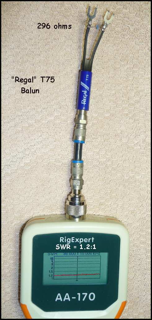 I recommend the use of these baluns if you can find them. I've used them with some of my designs and they seem to work nicely, are
well constructed for outdoor use and have decent SWR characteristics across the FM band (88 to 108Mhz).
I recommend the use of these baluns if you can find them. I've used them with some of my designs and they seem to work nicely, are
well constructed for outdoor use and have decent SWR characteristics across the FM band (88 to 108Mhz).
The picture shows a simple test setup using my RigExpert AA-170 set to 75 ohms. The SWR sweep on the AA-170 screen shows 1.2:1 SWR across
the band. The resistor combo totals to 296 ohms.
|
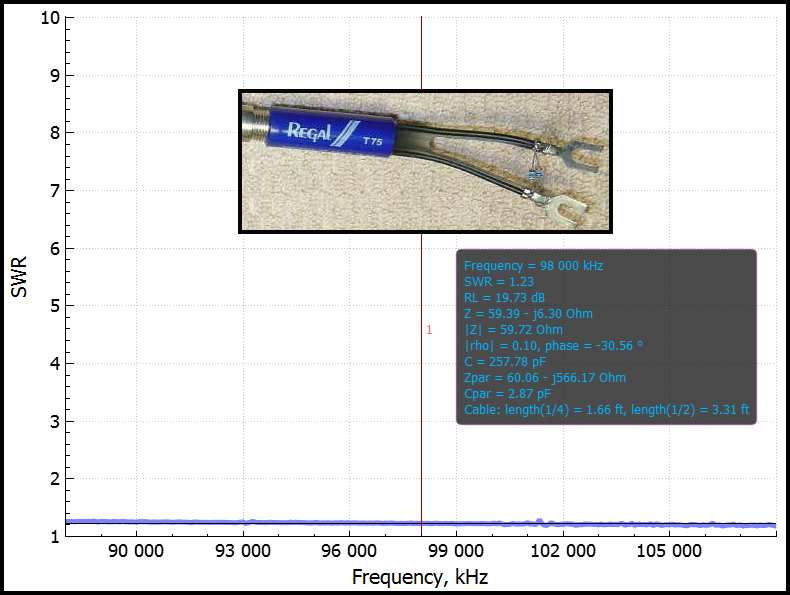
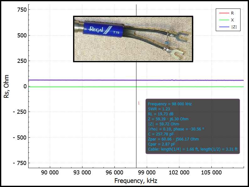 The left chart shows the SWR sweep across the FM band. It's very stable showing apx 1.2:1 SWR from the bottom to top of the band.
The right chart shows the Impedance sweep; apx 61 ohms with almost 0 ohms reactance. Can't ask much more than that.
The left chart shows the SWR sweep across the FM band. It's very stable showing apx 1.2:1 SWR from the bottom to top of the band.
The right chart shows the Impedance sweep; apx 61 ohms with almost 0 ohms reactance. Can't ask much more than that.
|
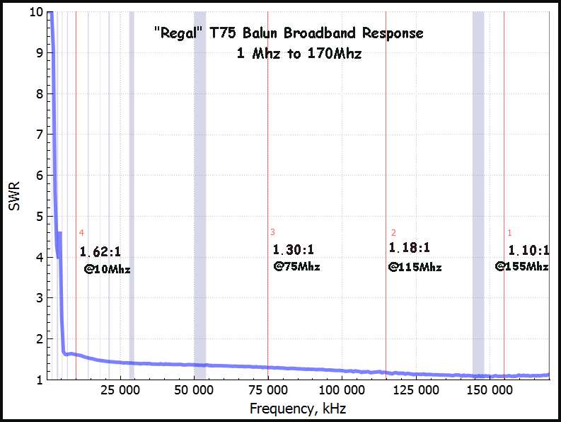 Using my RigExpert AA-170, I swept the full range of the instrument, 1Mhz to 170Mhz to quantize the performance of the Regal T75 Balun.
As expected, it has amazing bandwidth with the SWR dropping as the frequency increased. At the top end, 155Mhz, the SWR is 1.10:1
. . and dropping!
Using my RigExpert AA-170, I swept the full range of the instrument, 1Mhz to 170Mhz to quantize the performance of the Regal T75 Balun.
As expected, it has amazing bandwidth with the SWR dropping as the frequency increased. At the top end, 155Mhz, the SWR is 1.10:1
. . and dropping!
These are avialable are various sites . . here
|
You do not need these for use with the Stellar Lab 4el Yagi
since the balun is built in.
|
KUSC 4el Yagi
 Using Antenna Optimizer (AO), the as-delivered stock yagi was optimized for KUSC @ 91.5Mhz. The difference between
stock SL yagi @ 91.5Mhz vs optimized yagi is shown below;
Using Antenna Optimizer (AO), the as-delivered stock yagi was optimized for KUSC @ 91.5Mhz. The difference between
stock SL yagi @ 91.5Mhz vs optimized yagi is shown below;
Desc--- Stock----KUSC-Opt
F/G --- 7.5db ---- 9.3db
F/B --- 8.3db ---- 9.5db
SWR --- 2.43 ----- 1.03
The yagi was put up about 3 months ago and it did not have enough gain to reliably get KUSC during the "drop-out/fade"
events. The FM station's distance is 109 miles from my house so it's understandable. It was replaced by the 5el, then the
6el yagi (described in the subsequent sections).
 The summary report files can be downloaded and run in AO should you have the program.
The "stock" AO design file modeled @ 98Mhz is here
The "optimized" [KUSC @ 91.5Mhz] AO design file is here
The sketch shows the layout of the elements as well as the length of each half-element. Be careful to be accurate with the
dimensions shown to have the finished product work as indicated!
Download both files and rename the 'stock' file to "FMSL-STK.ANT" and "FMSL4ELO.ANT" to run with your version
of AO.
|
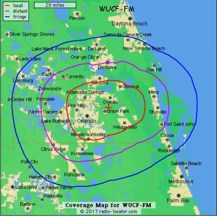 Joe, W0WD wants to receive WUCF FM @ 89.9Mhz in Orlando, FL apx 48miles from Cape Canaveral, FL. Using AO, all elements were
optimized and the results are:
Joe, W0WD wants to receive WUCF FM @ 89.9Mhz in Orlando, FL apx 48miles from Cape Canaveral, FL. Using AO, all elements were
optimized and the results are:
Desc--- Stock----WUCF-Opt
F/G --- 7.5db ---- 9.6db
F/B --- 8.3db ---- 6.8db
SWR --- 2.43 ---- 1.05
Download the file here and rename to FM4ELJD2.ANT to run in AO.
|
 The picture and sketch show how to buld the antenna. Note that you will need 2 60" sections of 3/8" dia alum tubing to use
for Dir1 and Dir2. The elements sent with the stock SL 4el yagi are too short to be used.
The picture and sketch show how to buld the antenna. Note that you will need 2 60" sections of 3/8" dia alum tubing to use
for Dir1 and Dir2. The elements sent with the stock SL 4el yagi are too short to be used.
The FM station broadcasts 360W horizontally and 5.6KW vertically . . so you may have to rotate
the yagi vertically depending on how far away you are from the transmitter. More station info:
here.
|
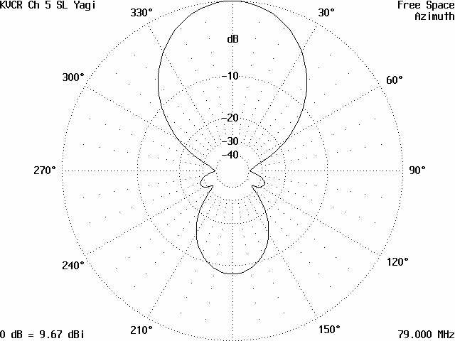
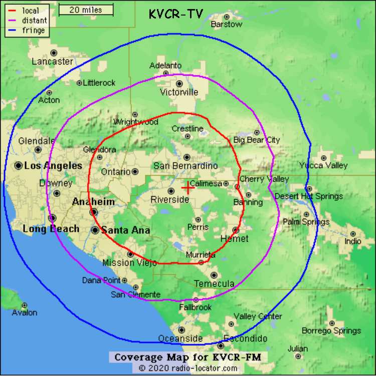 Bruce, KI6BPL wants to receive KVCR DT Ch5 @ 79 Mhz in Ramona, CA apx 68 miles from San Bernardino, CA. Using AO, all
elements were optimized and the results are:
Bruce, KI6BPL wants to receive KVCR DT Ch5 @ 79 Mhz in Ramona, CA apx 68 miles from San Bernardino, CA. Using AO, all
elements were optimized and the results are:
Desc--- Stock----KVCR-DT
F/G --- 7.5db ---- 9.7dB
F/B --- 8.3db ---- 8.2dB
SWR --- 2.43 ---- 1.08
Download the file here and rename to KVCR_SL.ANT to run in AO.
|
 The picture and sketch show how to build the antenna. Note that you will need 3 - 72" sections of 3/8" dia alum tubing to
use for the Refl, Dir1 and Dir2. The elements sent with the stock SL 4el yagi are too short to be used.
The picture and sketch show how to build the antenna. Note that you will need 3 - 72" sections of 3/8" dia alum tubing to
use for the Refl, Dir1 and Dir2. The elements sent with the stock SL 4el yagi are too short to be used.
The TV station broadcasts both horizontal and vertical signals at 25.8 kW so you should be able to mount the
antenna in either mode to receive the station. More station info:
here.
|
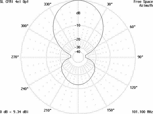
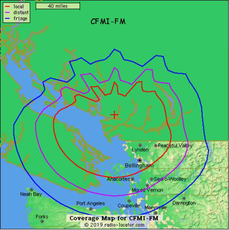 Jeroen, K7JBT wants to receive CFMI FM @ 101.1Mhz in Seattle, WA apx 115 miles from Vancouver, BC. Using AO, all
elements were optimized and the results are:
Jeroen, K7JBT wants to receive CFMI FM @ 101.1Mhz in Seattle, WA apx 115 miles from Vancouver, BC. Using AO, all
elements were optimized and the results are:
Desc--- Stock----CFMI FM
F/G --- 7.5db ---- 9.34dB
F/B --- 8.3db ---- 12.32dB
SWR --- 2.43 ---- 1.10
Download the file here and rename to SL_CFMI.ANT to run in AO.
|
 The picture and sketch show how to build the antenna. Note that you will need 2 - 60" (or 4 pieces - 30" length) sections
of 3/8" dia alum tubing to use for the Dir1 and Dir2. The REFL can be cut-down from the existing
reflector element. The director elements sent with the stock SL 4el yagi are too short to be used.
The picture and sketch show how to build the antenna. Note that you will need 2 - 60" (or 4 pieces - 30" length) sections
of 3/8" dia alum tubing to use for the Dir1 and Dir2. The REFL can be cut-down from the existing
reflector element. The director elements sent with the stock SL 4el yagi are too short to be used.
The FM station broadcasts with 100KW ERP from an antenna @ 2135ft above sea level. Since the station is 115 miles
away, you should mount the antenna as high as possible to give the maximum radio horizon possible.
More station info: here
|
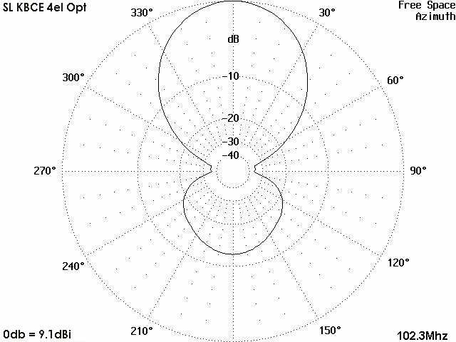
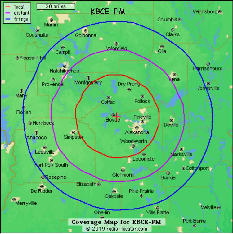 Chris wants to receive KBCE FM @ 102.3Mhz in Marksville, LA apx 45 miles from Boyce, LA. Using AO, all
elements were optimized and the results are:
Chris wants to receive KBCE FM @ 102.3Mhz in Marksville, LA apx 45 miles from Boyce, LA. Using AO, all
elements were optimized and the results are:
Desc--- Stock----KBCE FM
F/G --- 7.5db ---- 9.10dB
F/B --- 8.3db ---- 10.28dB
SWR --- 2.43 ---- 1.03
Download the file here and rename to SL_KBCE.ANT to run in AO.
|
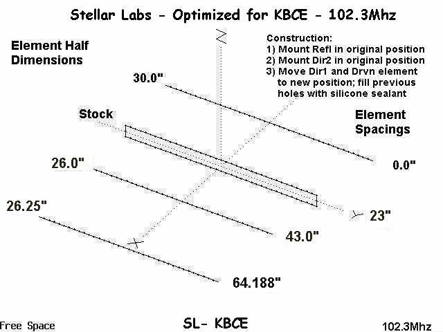 The picture and sketch show how to build the antenna. Note that you will need 2 - 60" (or 4 pieces - 30" length) sections
of 3/8" dia alum tubing to use for the Dir1 and Dir2. The REFL can be cut-down from the existing
reflector element. The director elements sent with the stock SL 4el yagi are too short to be used.
The picture and sketch show how to build the antenna. Note that you will need 2 - 60" (or 4 pieces - 30" length) sections
of 3/8" dia alum tubing to use for the Dir1 and Dir2. The REFL can be cut-down from the existing
reflector element. The director elements sent with the stock SL 4el yagi are too short to be used.
The FM station broadcasts with 21KW ERP from an antenna @ 289ft above sea level. Since the station is 45 miles
away, you should mount the antenna as high as possible to give the maximum radio horizon possible.
More station info: here
|
KBCE 4el Yagi Results
The antenna was constructed from a Stellar Labs (SL) 4el yagi with the Dir1 and Dir2 replaced with longer elements per AO design
requirements shown above. It was put up at 30+ft on a push-mast, feed with RG6 coax and three (3) coax chokes as shown in the pictures.
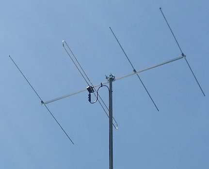
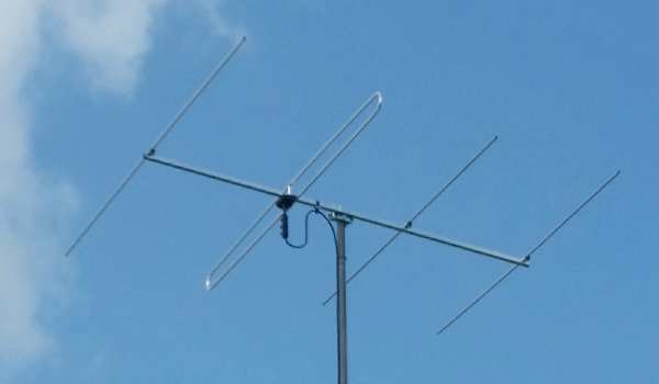
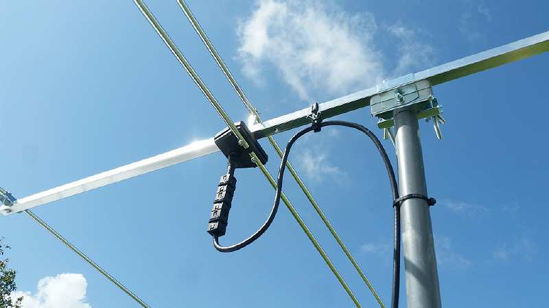 Chris wrote . . "Reception is great! KBCE, 102.3 has zero static. Other stations crystal clear even on the
back side. Picking up a 100k watt station in Baton Rouge @ 98.1Mhz (90 miles away) on the back side with a little static."
Another satisfied user . . . that's what I like!!
Chris wrote . . "Reception is great! KBCE, 102.3 has zero static. Other stations crystal clear even on the
back side. Picking up a 100k watt station in Baton Rouge @ 98.1Mhz (90 miles away) on the back side with a little static."
Another satisfied user . . . that's what I like!!
|
KUSC 5el Yagi
For KUSC @ 91.5Mhz, the yagi should have at least 9.5db F/G (109 miles) so that dictates a 5 or 6el beam. Preliminary design
show that 9.4db is attainable on the same boom (66") with 5els. This AO design shows good "specs" for the short boom.
Desc--- Stock----KUSC-Opt
F/G --- 7.4db ---- 9.4db
F/B ---13.8db ---- 9.4db
SWR --- 1.6 ------ 1.07
Download the design file here and rename it to "FLSL5ELO.ANT" to run in AO.
 The antenna was constructed today and the plots show good gain (9.4dB) w/ 9db F/B ratio. The right side chart shows the
dimension half-length pluse element spacing needed to obtain the F/G on a short boom. And that means, it doesn't have a lot
of operating bandwidth b/c it was designed for receiving KUSC @ 91.5Mhz. It is NOT a broad-band antenna.
The antenna was constructed today and the plots show good gain (9.4dB) w/ 9db F/B ratio. The right side chart shows the
dimension half-length pluse element spacing needed to obtain the F/G on a short boom. And that means, it doesn't have a lot
of operating bandwidth b/c it was designed for receiving KUSC @ 91.5Mhz. It is NOT a broad-band antenna.
The 'guts' consist of a stock Stellar Labs 4el yagi with a 66" boom length and an extra element. The construction of this
yagi is different; the boom is 0.709" [18mm] square, the elements are not tapered, are 0.392" in dia. The folded dipole driven
element extends above (1.8") and below (1.5") the boom center. Never have seen that consturction before but it looks fine.
Attached to the feed element is a waterproof 4:1 balun [300 to 75 ohm] transformer. There is no need for an external balun.
Overall it's very strong but light, apx 1.5 lbs, perfect for So Cal.
KUSC 5el Yagi Results
To say it worked as designed, is an understatement. Today's weather is cold (60F) and it has been lightly raining, so there's
absolutely no inversion. After boresighting the yagi to KUSC (322 degs), the Sony XDR showed three bars plus HD) signal . .
solid! But as the weather worsened, the HD) icon start to 'blink' meaning that the HD portion of the overall signal was
too weak to use the Sony internal HD decoder. It would come and go indicating that more F/G is needed. This yagi would be
good for the middle area, apx 50 miles max from KUSC.
The pics below compare the XLNC-4el (1st) with the KUSC-5el (2nd) and KUSC-6el (3rd) and lastly, the KUSC-7el.

 The supplied "manual" shows that the boom-to-mast clamp is between the driven el and reflector. When I mounted the 4el
yagi, the boom-mast clamp was at the beam's balance point which is just in front of the driven element. But for the 6el, the
boom-mast clamp is on the director 2 side of the 1st director, making for less interaction of the driven element.
The supplied "manual" shows that the boom-to-mast clamp is between the driven el and reflector. When I mounted the 4el
yagi, the boom-mast clamp was at the beam's balance point which is just in front of the driven element. But for the 6el, the
boom-mast clamp is on the director 2 side of the 1st director, making for less interaction of the driven element.
The 4el and 5el antennas have similar F/G, the difference being apx less than 0.5dB. So after looking at the performance of
both antennas, either the 4el or 5el are suitable for use up to 50- 60miles depending on the signal strength of the FM
station. KUSC employs 39KW while some use as little as 5KW.
|
KUSC 6el Long Boom Yagi
During some of the recent weather conditions (heavy rain and cold), the HD) is 'blinking (weak) and the analog signal dropped
to "2" bars! Albeit a short time, it did drop. Since I have two (2) Stellar Labs 4el yagis, there is enough material to make
a long boom 6el yagi. This design will be optimized for F/G as was the previous 5el yagi but on a long boom for significantly
more F/G.
Using AO, the design parameters are below. Being 109 miles from the KUSC xmitter site, I could use as much F/G as I can get.
To that end, here's my latest design; 6 els on a 8' - 9" boom.
Desc--- Stock---- KUSC-5el---- KUSC-6el
F/G --- 7.4db ---- 9.4db ------- 11.0db
F/B ---13.8db --- 9.4db ------- 11.3
SWR --- 1.6 ----- 1.03 ---------- 1.06
As before, download the design file here and rename it to "FLSL6ELO.ANT" to run in AO.
 The construction of the Stellar Labs yagi is a home-brewers delight; it is light but extremely strong. Every element is a
solid, one piece tube unlike other yagis where the element is rolled aluminum sheet so the tube has a "slit". It's very easy
to extend the boom using an "insert". The "seam" will be sealed so no moisture can penetrate.
The construction of the Stellar Labs yagi is a home-brewers delight; it is light but extremely strong. Every element is a
solid, one piece tube unlike other yagis where the element is rolled aluminum sheet so the tube has a "slit". It's very easy
to extend the boom using an "insert". The "seam" will be sealed so no moisture can penetrate.
Each yagi's boom is 66" long. Apx 41" will be cut from one yagi to make the required length, 105" + 2" inches for boom end.
I plan on joining the two booms with a some sort of a square dowel insert. It needs to be apx 0.640" L x 0.640" W to extend
the boom length to 8'-9" (105" + 2"). You will also need 3/8" aluminum tubing to make new elements since the SL stock elements
are too short.
The "picture" gives you an idea of what it will look like when complete.
|
 The left chart shows the AO design parameters in the azimuth view. Great F/G with little F/B ratio. F/B ratio is not important
where I am; all other FM stations are beamed from Mount Soledad and that puts their signal into the "side" of the antenna where
there's 30db or more side null.
The left chart shows the AO design parameters in the azimuth view. Great F/G with little F/B ratio. F/B ratio is not important
where I am; all other FM stations are beamed from Mount Soledad and that puts their signal into the "side" of the antenna where
there's 30db or more side null.
|
KUSC 6el Yagi Photos
 The yagi was built and here's some pics showing the construction. Most HAMs save aluminum as if it was gold. So I had a
good selection of aluminum tubing for this project. The main need was for an "square-insert" in order to join the
the two boom halves. Home Depot has a 5/8" x 5/8" x 36" square dowel
here for $2.41.
The yagi was built and here's some pics showing the construction. Most HAMs save aluminum as if it was gold. So I had a
good selection of aluminum tubing for this project. The main need was for an "square-insert" in order to join the
the two boom halves. Home Depot has a 5/8" x 5/8" x 36" square dowel
here for $2.41.
I picked through the stock and found one that measured 0.635" L x 0.635" W x 36" L. I used the complete piece and the
boom was razor straight. [4/14/19] However, about 2 years later, the director end started
to show some sag. So I used an aluminum 1/2" angle to remove the sag. Home Depot has different versions; this one is 1/2"
x 36" long for $1.98, shown
here
This morning I took down the 5el short boom yagi and installed the 6el long boom yagi. When I connected the coax to the
Sony XDR, there were 3-bars and FLASHING HD) symbol . . . same as before! With the no-inversion weather we are
experiencing, this is normal for a lower gain antenna. But this yagi is supposed to have enough gain and it's the main
reason why it was designed and built.
 My sadness turned to happiness after boresighting the yagi. The HD) was SOLID! 10 hrs later and it's still solid.
One main reason for the difference in beamwidth [BW] of the stock yagi, 67 degs vs 46 degs for the 6el yagi.
The KUSC beam heading is 332 degs per their location map above and the best HD) reception was found at 332 degs!
To say I'm pleased is an understatement. The yagi was supposed to give the extra gain that was needed but sometimes
"Murphy's Law" sets in!
I can state that if you want a LONG RANGE yagi, the 6el design is for you. 109 miles with 3bars and HD) solid!
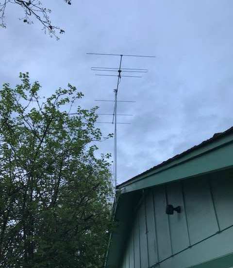
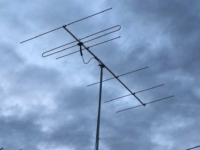 Bryne, N7BB wrote to me about constructing the 6el yagi to get KMHD near Portand, OR. He bought two (2)
stock SL yagis and made the 6el. It's mounted at 22ft above ground. The FM station is 111 miles away, runs 7.9KW from a
1400 ft elevation antenna. Here's two pictures of the completed antenna. Great job!
Bryne, N7BB wrote to me about constructing the 6el yagi to get KMHD near Portand, OR. He bought two (2)
stock SL yagis and made the 6el. It's mounted at 22ft above ground. The FM station is 111 miles away, runs 7.9KW from a
1400 ft elevation antenna. Here's two pictures of the completed antenna. Great job!
Download the design file for KMHD here and rename it to "N7BB6ELO.ANT" to run in AO.
Total boom length = 8ft 11"
Another version - SL 6el Short-Boom for FM Mid Band operation: F/G = 9.8db, F/B = 24.2dB on 6ft - 9inch boom length.
This yagi is designed for F/B ratio for mid-band (98Mhz) operation. Download the design file here
and rename it to "N7BB6ELZ.ANT" to run in AO.
|
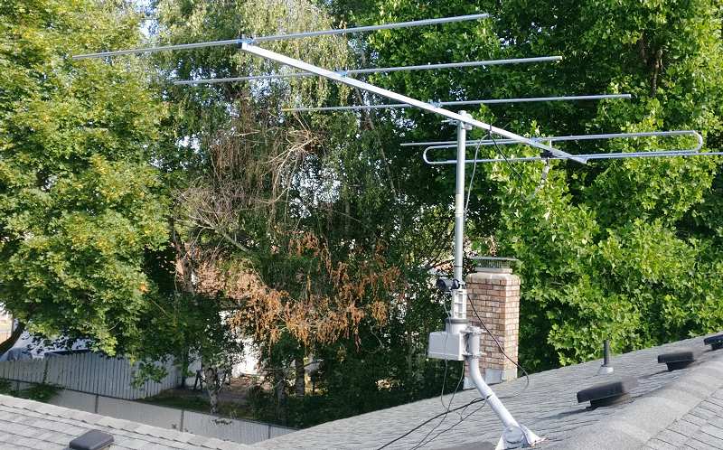
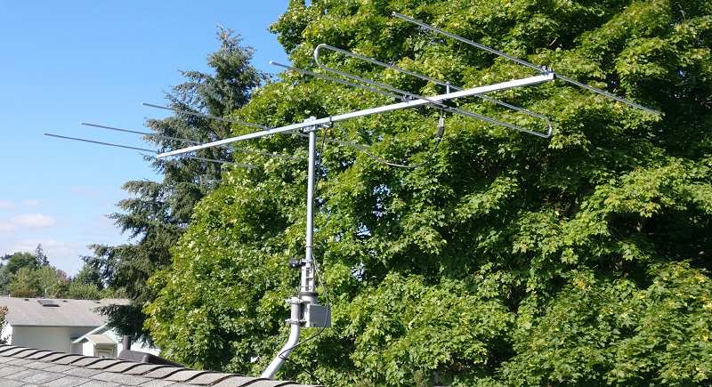 Ernie, W7DUH wrote to me about constructing the 6el yagi to get KIPO @ 89.3Mhz in Honolulu,HI, a distance of
2564 miles! ERP is 38.5KW. He bought two (2) stock SL yagis and made the 6el using a single piece 3/4" boom. It's
mounted on a rotator at 25ft above ground. Unfortunately, he built the 6el KUSC yagi @ 91.5Mhz not the one designed for
89.3Mhz. Here's two pictures of the completed antenna.
Ernie, W7DUH wrote to me about constructing the 6el yagi to get KIPO @ 89.3Mhz in Honolulu,HI, a distance of
2564 miles! ERP is 38.5KW. He bought two (2) stock SL yagis and made the 6el using a single piece 3/4" boom. It's
mounted on a rotator at 25ft above ground. Unfortunately, he built the 6el KUSC yagi @ 91.5Mhz not the one designed for
89.3Mhz. Here's two pictures of the completed antenna.
He wrote: "Thought I'd give you some followup on your 6 element antenna design for KUSC.
I am very impressed, it went from the antenna craft FM6 to the new antenna S9 to S9+39db on an SDRPlay! I'm also using a Sony
XDR-S3HD. Did all the mods you listed and went together without a hitch. Good tip you mentioned regarding using a clothe-tape
measure attached to the boom. Helped keep things very accurate. Overall it made for a sturdy antenna. Thanks for sharing your
expertise. Glad I could help you but sorry that the 89.3Mhz design was "lost" so it wasn't built!
|
FM Mid-Band 6el Yagi @ 98Mhz
I've receive requests for a FM mid band yagi so here it is. It is basically the KUSC yagi @ 91.5Mhz re-designed for the
middle of the FM band - 98Mhz. It is NOT broad-band but a narrow 'slot' antenna tuned for 98Mhz.
Using AO, the design parameters are below. The yagi is designed for F/G with little regard to the F/B ratio. The total
boom length is 8'-9" = 105" boom.
 Desc--- Stock---- KUSC-5el---- FM-Mid-Band
F/G --- 7.4db ---- 9.4db ------- 10.6db
F/B ---13.8db --- 9.4db ------- 13.2
SWR --- 1.6 ----- 1.03 ---------- 1.03
Download the design file here and rename it to "SL6EL98.ANT" to run in AO.
The construction of the Stellar Labs yagi is identical to that shown under the "KUSC 6el Yagi". Please follow the instructions
shown in that section to successfully build the antenna. You won't need extra 3/8" aluminum tubing since the elements supplied
w/ two (2) SL 4el Yagis can be cut to make the new element dimensions.
|
KUSC 7el Long Boom Yagi
For those who want the biggest yagi with max gain and have the material plus time to build it, here's the yagi for you!
As of yesterday, I had no plans to build it . . . but TODAY is a different story! I've started to build it.
 Using AO, the design info is shown below compared to the 5el and 6el yagis. It's been designed for MAX F/G and low SWR at
the design frequency. The comparison data shows;
Using AO, the design info is shown below compared to the 5el and 6el yagis. It's been designed for MAX F/G and low SWR at
the design frequency. The comparison data shows;
Desc--- Stock---- KUSC-5el---- KUSC-6el---- KUSC-7el
F/G --- 7.4db ---- 9.3db ------- 11.0db ------- 12.3db
F/B ---13.8db --- 10.5db ------- 11.3 ---------- 11.7db
SWR --- 1.6 ----- 1.03 ---------- 1.02 ---------- 1.04
As before, download the design file here and rename it to "FLSL7ELO.ANT" to run in AO.
|
AO Simulation: Free Space
 The left chart shows the AO predicted F/G and F/B ratio azimuth view. The yagi was designed for maximum F/G and 300 ohm
feed impedance: SWR = 1.04:1
The left chart shows the AO predicted F/G and F/B ratio azimuth view. The yagi was designed for maximum F/G and 300 ohm
feed impedance: SWR = 1.04:1
The F/B ratio has not been optimized b/c F/G is the most important parameter; all other FM stations are beamed from Mount
Soledad and that puts their signal into the "side" of the antenna where there's apx 30db or more side null.
|
AO Simulation: Over Gnd = 30 ft
 The left chart shows the AO simulation results for F/G and F/B ratio - azimuth view and to the right, the EL view.
The antenna was designed for maximum F/G and feed impedance = 300 ohms. SWR = 1.21:1 Other parameters were not
considered.
The left chart shows the AO simulation results for F/G and F/B ratio - azimuth view and to the right, the EL view.
The antenna was designed for maximum F/G and feed impedance = 300 ohms. SWR = 1.21:1 Other parameters were not
considered.
The F/B ratio was not optimized b/c only the F/G is important; all other FM stations beamed from Mount Soledad puts
their signal into the "side" of the antenna where there's apx 30db or more null.
|
7EL Construction
5/1/19
The boom length is 12' 6" + 2" so it requires a strong boom to support the length. The boom material of the SL yagi
is not strong enough b/c it's 18mm* (0.710") square has a wall thickness of 0.7mm
(0.033") so it's too flimsy to support the long boom length plus 7 elements w/o sagging. Of interest is the difference in
weight; the SL boom weighs 1 lbs whereas the new boom weighs 1.9 lbs (for the same length]. The formula for
calculating the weight of an alum tube is WT(lbs) = 3.70 x (OD-W) x W where OD = outside dia; W = wall thickness.
Along that note, do NOT try to seam to boom pieces together; I learned a lesson from my build of the 6el yagi. I
seamed the back section (holds two (2) directors) to the main boom. Worked OK for a few years but then started to sag. A one
piece boom is the only way to build this or any long boom yagi.
 I acquired a scrap piece of 3/4" x 3/4" x 1/16" (0.0625") wall alum square tubing and made the mockup you see here.
There are three (3) areas that need to be modified so the SL yagi parts will successfully mount on the new larger
boom. It's not a big deal but these areas need to be modified so the larger, stronger boom can be employed.
I acquired a scrap piece of 3/4" x 3/4" x 1/16" (0.0625") wall alum square tubing and made the mockup you see here.
There are three (3) areas that need to be modified so the SL yagi parts will successfully mount on the new larger
boom. It's not a big deal but these areas need to be modified so the larger, stronger boom can be employed.
 The picture shows that the groved-area must be enlarged . . by apx 20mils on both sides. I used a medium rat-tail
file and kept checking progress. Also not a hard task . . there's plenty of depth to the plastic side rails on the driven
element so there's no danger of breaking them. That written, just be careful!
The picture shows that the groved-area must be enlarged . . by apx 20mils on both sides. I used a medium rat-tail
file and kept checking progress. Also not a hard task . . there's plenty of depth to the plastic side rails on the driven
element so there's no danger of breaking them. That written, just be careful!
Next cut apx 1/16" from the alum-spacing tube used to support the folded-dipole element. It's not exact but this makes up for
the added height from the old SL boom (0.710") and the new boom (0.75"), a difference of apx 0.040" and the original was too
long to start. Now it's correct.
 The 2nd area is the boom-to-element clamp. The spacing is apx 0.710" and it needs to be opened apx 20mils on each side in
order for the new 3/4" sq alum boom to slide into the area. I used a Dremel tool with a hard carborundum disk . . gently work
the tool to the each side and take off the required material until the boom slides into the groves as shown in the oval
highlighted area of the picture. Don't forget the other side!
The 2nd area is the boom-to-element clamp. The spacing is apx 0.710" and it needs to be opened apx 20mils on each side in
order for the new 3/4" sq alum boom to slide into the area. I used a Dremel tool with a hard carborundum disk . . gently work
the tool to the each side and take off the required material until the boom slides into the groves as shown in the oval
highlighted area of the picture. Don't forget the other side!
Last, and probably the hardest, is to make the larger 3/4" tubing fit into the SL B-to-M clamp (0.710"). Since the metal is
quite strong you really can't "reshape" it . . recommend that you use your bench vise. You MUST have one to do this
job properly IMO. You need the leverage the bench vise provides in order to re-form the bracket for the 3/4" sq boom.
 You need to reform the clamp-bracket to fit the larger 3/4" tubing; so place the tubing and clamp in the vise and GENTLY start
closing the jaws. After working the tubing to the bottom of the clamp (it won't go all the way to the bottom), turn the whole
assy in the vice so the you can now GENTLY bend the sides to be ALMOST straight. Do NOT try to bend them to be 90 degs
b/c it won't happen! And doesn't need to.
You need to reform the clamp-bracket to fit the larger 3/4" tubing; so place the tubing and clamp in the vise and GENTLY start
closing the jaws. After working the tubing to the bottom of the clamp (it won't go all the way to the bottom), turn the whole
assy in the vice so the you can now GENTLY bend the sides to be ALMOST straight. Do NOT try to bend them to be 90 degs
b/c it won't happen! And doesn't need to.
 Now fit it to the mast piece and check that when the two (2) screws are tightened, that the boom is PARALLEL to the
mast-mount piece. Odds are it won't be so drill the back side hole (enlarge) using 3/16" drill bit so the hole is
ENLONGATED such that when the bolt is inserted and tightened down, the boom is parallel. You may have to do this
procedure a few times before it is level.
Now fit it to the mast piece and check that when the two (2) screws are tightened, that the boom is PARALLEL to the
mast-mount piece. Odds are it won't be so drill the back side hole (enlarge) using 3/16" drill bit so the hole is
ENLONGATED such that when the bolt is inserted and tightened down, the boom is parallel. You may have to do this
procedure a few times before it is level.
In order to speed the drilling of the new boom, I used a tape measure "locked" to the boom to mark the points as shown. I
used a 11/64" drill bit making holes at the indicated points.
*
I did find one company that supplies metric size alum square tubing: MetricMetal in Maumee, OH.
They can supply 18mm x 18mm x 2.0mm wall thickness in 16ft lengths. Cost is reasonable but shipping to CA makes it
prohibitive.
|
7EL Pictures
 5/4/19
Took most of the day but it's up . . all 12ft 8in of it @ 30ft over ground! It was windy early through mid-day,
finally around 4:30pm, the wind stopped! The balance point was exactly where I thought it would be; a few inches in front
of Dir 2. Don't see any sagging from front to back. I listened to KUSC from apx 5pm - to past midnight . . solid signal w/
HD> and no fades.
5/4/19
Took most of the day but it's up . . all 12ft 8in of it @ 30ft over ground! It was windy early through mid-day,
finally around 4:30pm, the wind stopped! The balance point was exactly where I thought it would be; a few inches in front
of Dir 2. Don't see any sagging from front to back. I listened to KUSC from apx 5pm - to past midnight . . solid signal w/
HD> and no fades.
Some of the elements that were used came from the 6el version. They were made from 3/8" inch alum tubing, so I had to re-run
the AO simulation to quantify what the diameter difference meant to the yagi's performance. Ended up re-positioning the
elements to get better F/G = 12.3dB and SWR: 1.04:1.
5/6/19
Today, it rained and the HD> symbol was blinking. After the rain, it came back solid. I performed a
"boresight" procedure the same way I did with the 6el. Turning the yagi from LEFT to RIGHT extreme (where
the HD> symbol starts to blink) it was 10-15 degs further on each side than the 6el. Since the 7el has a 40deg BW
(6el = 45 deg BW), that can only mean it has more F/G. This is a nice way to find the yagi's center point; as you rotate
to each extreme, mark the point on the 'clamp'. When complete, the middle is the sweet-spot! The design and build
was worth the effort!
5/9/19
 The mast appeared to be bent from 35+ years of use in the California weather, it finally rotted from the inside and developed
a nice crack as shown in the left picture. So after dismantiling the 6el, building the 7el and putting it up, I had to take
it down (which meant disassembling everything) to replace the mast. Bought a 12ft section of 1-3/8" dia alum tube w/ 0.065"
wall. Added a 5ft section; 1-1/2" on top to bring it up to apx 17ft. As you can see, the old steel mast had rotted through
and was a puff-of-wind away from breaking!
The mast appeared to be bent from 35+ years of use in the California weather, it finally rotted from the inside and developed
a nice crack as shown in the left picture. So after dismantiling the 6el, building the 7el and putting it up, I had to take
it down (which meant disassembling everything) to replace the mast. Bought a 12ft section of 1-3/8" dia alum tube w/ 0.065"
wall. Added a 5ft section; 1-1/2" on top to bring it up to apx 17ft. As you can see, the old steel mast had rotted through
and was a puff-of-wind away from breaking!
|
 5/18 - 31/19 - 7EL Measurements: MFJ-226 & R/E AA-170
The MFJ-226 GNA performs a 50 ohm analysis only. The KUSC 7el Yagi requires a GNA device to accomodate 75 ohms. It
s/b obvious that starting from the folded dipole (FD) thru the 4:1 balun ending in the RG6 feed line, all results
should reflect 75 ohm system impedance. So the charts shown w/ "green" border are MFJ-226 @ 50 ohm and the black
border with the summary chart are AA-170 @ 75 ohms.
 Before you use a piece of coax, you might want to check it out . . the chart shows a 12ft section of RG6 with an open shield
on one end. You should check the coax* before you use it to make SWR, RXZ, RL, etc.
measurements! The coax is low loss with high reflection that mimics a hi-Q antenna's resonance. So instead of measuring the
"antenna", you are making completely bogus measurements! Don't be fooled.
Before you use a piece of coax, you might want to check it out . . the chart shows a 12ft section of RG6 with an open shield
on one end. You should check the coax* before you use it to make SWR, RXZ, RL, etc.
measurements! The coax is low loss with high reflection that mimics a hi-Q antenna's resonance. So instead of measuring the
"antenna", you are making completely bogus measurements! Don't be fooled.
[ *A normal piece of RG6 should not show "resonance" - but a rippled-SWR sweep at a more or
less constant SWR based on the impedance mismatch.]
OK, back to the 7el Yagi: Hooked up each GNAnalyzer to the feed line (apx 27ft- RG6), made measurements and stored them in
each Analyzer. After finding out how to download the charts, I made much better quality charts using "PrtSc" and my
"LabView" program!
 MFJ-226:
The 7el is resonant at 91.9Mhz . . about 400Khz off from 91.5Mhz. The charts show analysis results
referenced to 50 ohms rather than the actual medium of 75 ohms. The AA-170 analysis charts are shown below.
MFJ-226:
The 7el is resonant at 91.9Mhz . . about 400Khz off from 91.5Mhz. The charts show analysis results
referenced to 50 ohms rather than the actual medium of 75 ohms. The AA-170 analysis charts are shown below.
|
 AA-170:
The 7el is resonant at 92.3Mhz . . about 800Khz off from 91.5Mhz. The charts show IMPEDANCE results
referenced to 75 ohms rather than 50 ohms. The "green" inserts show the complete measurements of the 7el yagi.
AA-170:
The 7el is resonant at 92.3Mhz . . about 800Khz off from 91.5Mhz. The charts show IMPEDANCE results
referenced to 75 ohms rather than 50 ohms. The "green" inserts show the complete measurements of the 7el yagi.
Bottom line, being "off" (400Khz=MFJ; 800Khz=R/E) isn't a big deal either? I will, at some point, perform a OSL
[Open,Short, Load] local calibration so that the 27ft of RG6 will be taken into account to see what difference it makes.
5/31/19 - Comments: MFJ-226 and R/E AA-170
Basically, the results of AA-170 were the same as MFJ-226 when both are set to a 50 ohm
system. When the AA-170 is correctly set to 75 ohm system, the results are slightly different. The KUSC 7el Yagi
resonance: R/E = 92.3Mhz; MFJ = 91.9Mhz.
 In order to see that they are the same, please check-out the "SWR" charts. The pictures show both GNAs and are marked
accordingly. If you take the time to compare the "RED" rectangle box in the 1st pic
with the 2nd picture, you'll see that the SHAPEs of both charts are almost identical! The
numbers are slightly different but close. [Right side chart was made with AA-170 = 50 ohm system]
In order to see that they are the same, please check-out the "SWR" charts. The pictures show both GNAs and are marked
accordingly. If you take the time to compare the "RED" rectangle box in the 1st pic
with the 2nd picture, you'll see that the SHAPEs of both charts are almost identical! The
numbers are slightly different but close. [Right side chart was made with AA-170 = 50 ohm system]
The provided SW for graph plots is pretty bad and that's being kind! The MFJ sw is yards better; the RE sw was written
by a grade-schooler! It's TERRIBLE as is the FW in the AA-170.
|
Stellar Labs Folded Dipole
 [5/16 - 31/19]
Some have asked . . where is the Stellar Labs Folded Dipole (SL FD) resonant?? Using Antenna Optimizer (AO), the as-delivered
stock feed assy was analyzed for resonant freq as is (27.75") and what length should it be for; 98Mhz, 91.5Mhz, 104.9M and
other frequencies. A simple folded dipole model was setup with dimensions as shown. Results:
[5/16 - 31/19]
Some have asked . . where is the Stellar Labs Folded Dipole (SL FD) resonant?? Using Antenna Optimizer (AO), the as-delivered
stock feed assy was analyzed for resonant freq as is (27.75") and what length should it be for; 98Mhz, 91.5Mhz, 104.9M and
other frequencies. A simple folded dipole model was setup with dimensions as shown. Results:
RF-FS = Res Freq-Free Space; RF-G = Res Freq-Over Ground
Hlf-Lng --- RF-FS --- RF-G ---- Remarks ---- Notes
27.75" ---- 95.40 ---- 95.90 ----- stock ----- D/L file: DPLSLRES.TXT here for AO
25.25" ---- 104.9 ---- 104.5 ----- -2.50" ---- Freq = constant; length FS = 25.25" : OG = 25.00"
*29.00" --- 91.50 ---- 91.00 ----- +1.25" ---- Length = constant
*varies --- 91.50 ---- 91.50 ----- +1.25" ---- Freq = constant; length FS = 29.0 : OG = 28.80
27.00" ---- 97.80 ---- 97.40 ----- -1.00"
*For KUSC = 91.5Mhz, the data is shown two (2) ways: for constant "LENGTH" and "FREQ".
So out-of-box, the SL FD (by itself) is resonant at 95.4Mhz in Free Space (FS) and moves up frequency when simulated Over
Ground @ 30 ft to 95.9Mhz. Resonance set to where reactance = j 0
(+/- 3).
Note that the frequency variation is extreme at LOW HEIGHTs such as 8 - 10ft. It is best to use the antenna at heights
GREATER than 25ft. At 30ft, there is little variation.
Please note that using the Refl and 1st Dir in my designs, it is possible to "force" a 300 ohm feed impedance by length
and/or position variation so it is NOT necessary to SHORTEN or LENGTHEN the SL FD itself. If you want to use it as a
stand-alone FD, then it may need to be altered.
Network Analyzer: MFJ-226
 Bought a MFJ-226 and it arrived just after I completed the section above. So I connected it up to the SL FD with as-short-
as-possible [2.5" including F-connectors] piece of RG6. It was hung from my wood fan blades and those make a great "holding"
fixture. I was pleasantly surprised by the SWR and Impedance sweeps even with the obvious home-brew test bed!
In the "old-days" you'd have a room full of equipment to do this job!
Bought a MFJ-226 and it arrived just after I completed the section above. So I connected it up to the SL FD with as-short-
as-possible [2.5" including F-connectors] piece of RG6. It was hung from my wood fan blades and those make a great "holding"
fixture. I was pleasantly surprised by the SWR and Impedance sweeps even with the obvious home-brew test bed!
In the "old-days" you'd have a room full of equipment to do this job!
On the third (3) day after receiving the unit, the MFJ-226 died!! Heard and read of poor quality of these units esp failures
due to poor soldering but my unit appeared to be "solid". It started to fail by making intermittent "high" readings; ie,
measuring a known 50 ohm load would come up as 56 ohms; later the same load would measure 109 ohms. When it finally failed,
the 50 load measured 999.9 ohms! It appeared that there's a problem with the N-female connector and its connection to
the main PWB. So it went back . . . never to return!
Stellar Labs 4:1 Matching Balun
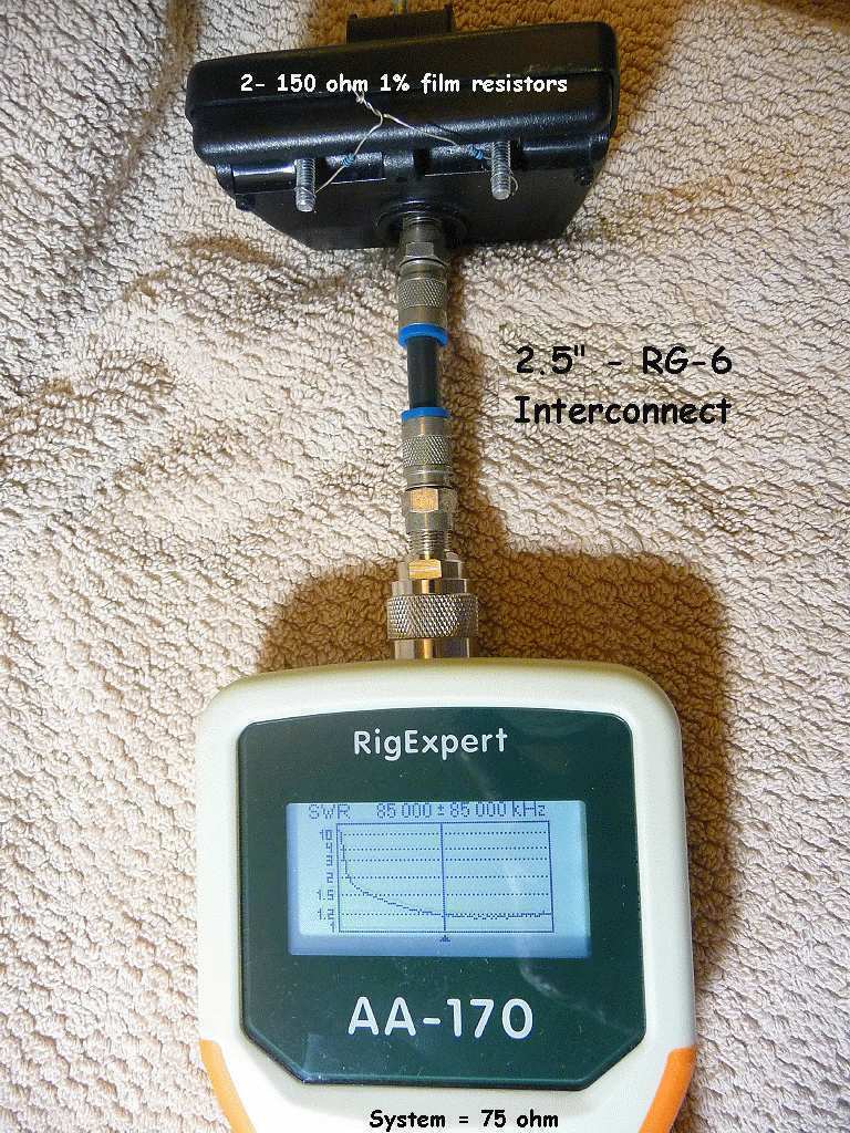
 Since my MFJ-226 is gone, I used the R/E AA-170 to measure the properties of the SL FD matching network. Looking inside at
the workmanship leaves one with questions whether this hodge-podge really works?? So naturally, one of the easier ways is
to use a GNA hooked to the terminals.
Since my MFJ-226 is gone, I used the R/E AA-170 to measure the properties of the SL FD matching network. Looking inside at
the workmanship leaves one with questions whether this hodge-podge really works?? So naturally, one of the easier ways is
to use a GNA hooked to the terminals.
Well, good news. . . they do work! Tested two and they both measure identically! The pictures show my test-setup and two
(2) sweeps; Full FM band and full AA-170 (1M to 170M) band. Click on each chart for the details and marker information.
The GNA proved that you must use a 300 ohm resistor to test the balun: SWR = 1.18:1 so the
transformer is impedance sensitive.
|
 MFJ-226:
These measurements were made outside on a 10ft pole so the FD was clear of obstacles with the MFJ-226 default mode of
50 ohm.
MFJ-226:
These measurements were made outside on a 10ft pole so the FD was clear of obstacles with the MFJ-226 default mode of
50 ohm.
Meaurements were made over the full FM band (88M - 108M) since it easily can be changed when making measurements on-the-fly.
As you can see, there are some "variations" that are due to the 50 ohm analysis of a 75 ohm system. SL FD resonant
frequency = 97.3Mhz
 AA-170:
These measurements were made over the full FM band as with the MFJ except the AA-170 was set to 75 ohms system. Note there
isn't the "wild" variations due reflections seen when a 75 ohm system is modeled using 50 ohm analysis. SL FD resonant
frequency = 97.1Mhz
AA-170:
These measurements were made over the full FM band as with the MFJ except the AA-170 was set to 75 ohms system. Note there
isn't the "wild" variations due reflections seen when a 75 ohm system is modeled using 50 ohm analysis. SL FD resonant
frequency = 97.1Mhz
An Anomaly!:
Using the full length (stock) SL FD, measurements were made a "low" height and strange things happen! Actually, not that
strange since we all know that ground effects will distort/force different behavior from any antenna. Not any different with
the SL FD.
 Here's what happens to the SL FD at apx 5ft over ground: the resonant frequency goes to
101.3Mhz . . . BION! Thought something had broken . . but no all was ok. AO confirmed
this also.
Here's what happens to the SL FD at apx 5ft over ground: the resonant frequency goes to
101.3Mhz . . . BION! Thought something had broken . . but no all was ok. AO confirmed
this also.
|
Radio Shack Corner Reflector for OTA
 Many years ago, I bought the RS UHF Corner Reflector antenna for receiving but never used it. About six years ago, I decided
to drop my cable connection for Over-The-Air (OTA) HDTV reception. So the cable company was waived bye-bye and I put the
antenna up on a 15' mast at apx 30' over ground. The added "director" for Ch 10 is explained here.
Many years ago, I bought the RS UHF Corner Reflector antenna for receiving but never used it. About six years ago, I decided
to drop my cable connection for Over-The-Air (OTA) HDTV reception. So the cable company was waived bye-bye and I put the
antenna up on a 15' mast at apx 30' over ground. The added "director" for Ch 10 is explained here.
|
 I've been bitten by the "HD" bug so I replaced my garage FM rcvr with a
Kenwood KDC-HD262U rcvr.
Features a superb FM rcvr with both digital and analog decoders. If the digital fades or drops out, it switches to the analog
mode. Has a single CD player and a USB input. Output power is 22 Watts RMS @ 4 channels and requires 12V which is supplied
by small Astron power supply.
I've been bitten by the "HD" bug so I replaced my garage FM rcvr with a
Kenwood KDC-HD262U rcvr.
Features a superb FM rcvr with both digital and analog decoders. If the digital fades or drops out, it switches to the analog
mode. Has a single CD player and a USB input. Output power is 22 Watts RMS @ 4 channels and requires 12V which is supplied
by small Astron power supply.
Has digital DSP featuring an "EQ Pro" section that lets you tailor the sound to fit your speakers. A superb feature. Price
was as low as $60. Recently, the Amazon price was $99 with free shipping but as of today, they no longer offer the radio
for sale. However, other vendors still carry the radio.
The picture shows receiving KUSC @ 91.5Mhz with both HD) and ST modes. Not bad for 109 miles to the xmitter site.
|
New Sony XDR Receivers
 [4/18/19]
Many years ago, I bought the Tivoli Model One AM/FM receiver for my wife to use in her bathroom. It features a surperb
ANALOG FM receiver and has an amazing wide frequency response from a small woofer. The cabinet is vented on the
bottom and that's what extends the frequency response from a 'box' that measures 8.375" x 5.25" x 4.5".
[4/18/19]
Many years ago, I bought the Tivoli Model One AM/FM receiver for my wife to use in her bathroom. It features a surperb
ANALOG FM receiver and has an amazing wide frequency response from a small woofer. The cabinet is vented on the
bottom and that's what extends the frequency response from a 'box' that measures 8.375" x 5.25" x 4.5".
The "full-range" speaker is only 3" dia. The bottom facing port does wonders but I can't find the specs for the increased
frequency response. This is one of the early models that doesn't have "bluetooth" function. However, it is rare b/c of the
dark cobalt blue colored face with a cherry cabinet.
[4/19/19]
Received a Sony XDR-S10HDip FM rcvr and have replaced the Tivoli with the Sony. Why? Today, the propagation
from the KUSC broadcast site to my home (109 miles) was poor and it was almost impossible to receive the station due to the
strong local interference from three (3) nearby FM stations at 91.1, 91.7 and 92.1. They just wipe out the Tivoli's front end.
That's the difference between an analog front end vs the FIR (Finite Impulse Response) filters in the Sony. In the family
room the Sony XDR-F1HD was playing away as if KUSC was the only station on the band!
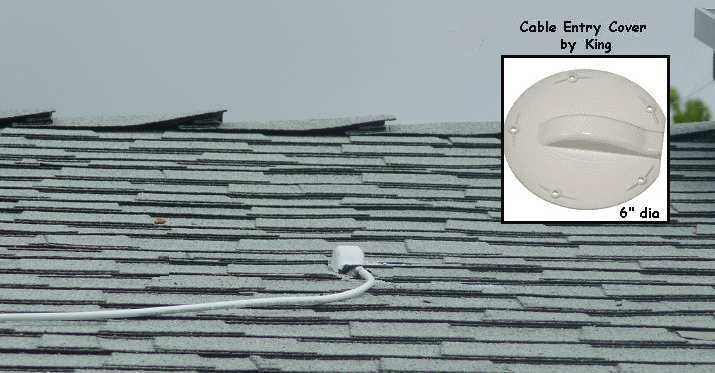 To add the new Sony XDR-S10HDiP receiver in the main bathroom I had to make a decision. Since my attic is full of loose-fill
cellulose insulation, I certainly didn't want to crawl through it for two reasons . . can't see the floor beams and the
insulation would bury me! So I routed the coax over the roof and dropped it into the attic directly above the main bathroom.
The hole was patched by using an RV cable entry cover as shown. Works great!
To add the new Sony XDR-S10HDiP receiver in the main bathroom I had to make a decision. Since my attic is full of loose-fill
cellulose insulation, I certainly didn't want to crawl through it for two reasons . . can't see the floor beams and the
insulation would bury me! So I routed the coax over the roof and dropped it into the attic directly above the main bathroom.
The hole was patched by using an RV cable entry cover as shown. Works great!
 The picture show how it was installed in the main bathroom. I chose the ceiling mount since it was the easiest to do w/o
having to fish a wire up the wall into the attic.
The picture show how it was installed in the main bathroom. I chose the ceiling mount since it was the easiest to do w/o
having to fish a wire up the wall into the attic.
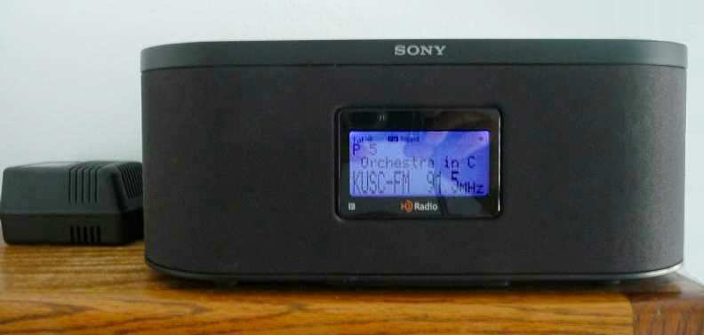 The main operating difference between the F1HD and S10HD is the TONE control that is built into the MENU. It
allows you to "correct" the TREBLE and BASS to fit the room and your ears. There's a SURROUND sound
feature that expands the audio to fill the room with non-directional sound. Since the chip technology is the same as that
in the F1HD, it receives identically.
The main operating difference between the F1HD and S10HD is the TONE control that is built into the MENU. It
allows you to "correct" the TREBLE and BASS to fit the room and your ears. There's a SURROUND sound
feature that expands the audio to fill the room with non-directional sound. Since the chip technology is the same as that
in the F1HD, it receives identically.
I downloaded the Service Manual for XDR-S10HDiP and it shows that each speaker is high-compliance 2.7" dia with a 1.8"
oval shaped port running apx 5" to the rear of the cabinet. The sound really belies such a compact setting!
Looking at the electronics schematic shows heavy use of ICs instead of individual transistors used in the F1HD. Also
a large number of voltage regulators designed with ICs, another big improvement. Scanning the output path from the DSP
Tuner for the LEFT/RIGHT audio showed no circuit components that would cause extreme frequency roll-off as was the case
in the F1HD. The audio pre-amplifier and power amplifier outputs are ICs, not discrete transistors. All of these
improvements account for the clean, powerful (3W/spkr) audio output.
It does appear that Sony also learned valuable lessons from the F1HD design and these were incorporated in the S3HD and
S10HD. The internal power supply caused extremely high temperatures inside the chassis, so it was moved to the external
'wart' that is shown in the picture above. The unit (transformer+filter caps) supplies the "raw" +12V and +7V to the main
unit. They also added a small fan in the back-side main unit that moves air that results a cool running radio with no heat
problems.
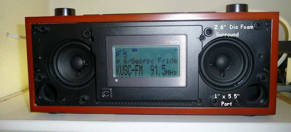
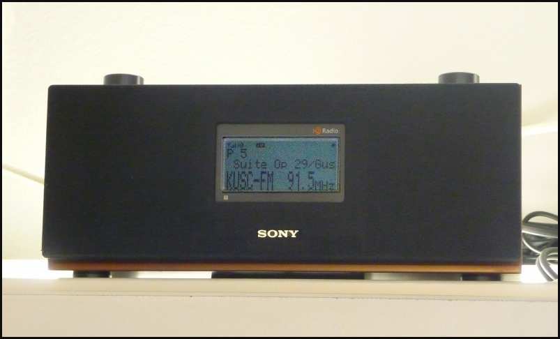 [4/23/19]
I've also purchased a Sony XDR-S3HD FM rcvr and it arrived today. Set it up in my office by employing the first (1st)
FM Distribution Amplifier output with apx 40ft of RG-6 coax. Mounted on top of the cabinets near the ceiling so it projects
full sound into the room. The right picture has the front grill removed showing the speaker detail. Note the port for lower
bass response. The cherry finish of the cabinet and black grill give it a retro look.
[4/23/19]
I've also purchased a Sony XDR-S3HD FM rcvr and it arrived today. Set it up in my office by employing the first (1st)
FM Distribution Amplifier output with apx 40ft of RG-6 coax. Mounted on top of the cabinets near the ceiling so it projects
full sound into the room. The right picture has the front grill removed showing the speaker detail. Note the port for lower
bass response. The cherry finish of the cabinet and black grill give it a retro look.
It has the same TONE and SURROUND features that the S10HDiP. It's the same chip set in all three Sony FM units.
Only the F1HD has the "treble" rolloff problem which is NOT due to the chip set but the electrical design to prevent
ultrasonic noise from feeding into and through the preamp.
Sony XDR-S3HD and XDR-S10HDiP Performance Comments
After a few days use, here are some observations for both units. Nothing about the F1HD since it is a 'tuner' and doesn't
have speakers as the S3 and S10 have.
Both front ends (DSP Tuner) are identical and receive the KUSC-FM signal from Los Angeles equally well. When one rcvr's HD
signal starts to drop, all rcvrs do the same thing. You would expect that from rcvrs with identical chip technology but
this just proves it.
The operating controls are a little different and it takes some time to get used to the differences. For the S3; the TONE
control on the remote is engaged by pressing it but to change the parameters (TREBLE, BASS, SURROUND), you need to press the
TUNE/SELECT buttons either UP (+) or DOWN (-) and then press ENTER when you're happy with the selection. For the S10, there's
a SURROUND button so it can be directly pushed to turn the feature on or off. Of course, the LAYOUT of both remotes is
different so there's a little barrier to overcome!
Here's a quick comparison between the two FM receivers:
---Function----- -------S3 ------- ----------S10-------
Speakers -------- 6.6cm - 4 ohm ------- 6.6cm - 8 ohms
Pwr Out ---------- 2.8W/spkr ----------- 3.3W/spkr
Circuitry --------- Single Ended --------Full Differntial
Coupling ---------- 1000 uf -------------- DC coupled
The speakers are the same size in both receivers, only the impedance is different. Each speaker has a large magnet and foam
surround making them highly compliant for their small size.
The S3's ouput is conventional - single ended drive with ground reference through 1000uF cap to each speaker. Contrasted with
the "star" of the show is the S10's full differential output drive - DC coupled to the
speakers. It's capable of producing very low frequencies limited only by the speaker's compliance. So it's not a
mystery why the S10's audio is cleaner and produces a better defined stereo image.
Both units SURROUND feature is noteworthy since it does broaden the audio wavefront to be much larger than the unit's physical
speakers. And you can decrease the volume with it selected.
|
|
[4/19-23/19]
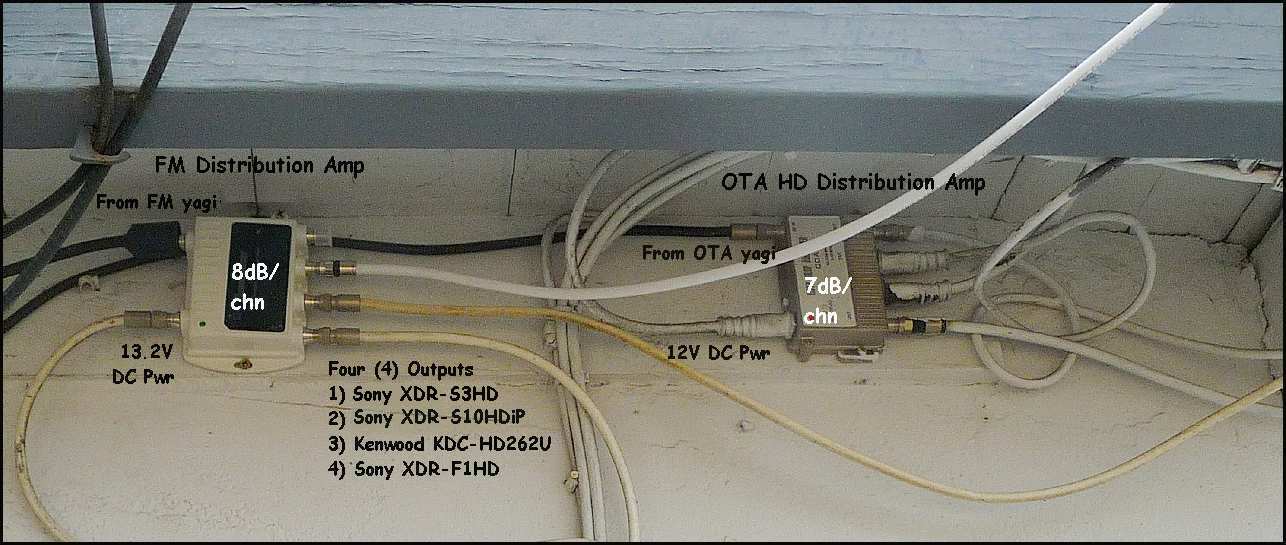 In order to ensure adequate signal to all four (4) FM rcvrs and OTA signal to four (4) HDTVs in my home, I added two (2)
distribution amps; a 4 channel FM and a 4 channel VHF/UHF. FM on the left; OTA on the right.
As the picture shows, both units are mounted under the eave so it is safe from rain and sun that could produce damage.
In order to ensure adequate signal to all four (4) FM rcvrs and OTA signal to four (4) HDTVs in my home, I added two (2)
distribution amps; a 4 channel FM and a 4 channel VHF/UHF. FM on the left; OTA on the right.
As the picture shows, both units are mounted under the eave so it is safe from rain and sun that could produce damage.
Both amps operate on their respective signals; the FM amplifier sends it out the amplified signal to three (3) output ports
with 8dB/channel gain. Note that all four outputs are amplifiers and NOT "preamps" in that there's no input
gain, just output gain to buffer the respective signals for long coax cable runs.
The FM cable to the garage rcvr is apx 70' producing apx 3dB loss. The bathroom receiver, Sony XDR-S10HDiP, is next at apx
2db loss. The newly arrived Sony XDR-S3HD has been added to the first (1st) output when it arrived today.
The HDTV input from the OTA yagi is amplified by 7dB/channel and the four channels are distributed via existing coax
to each HDTV in my home. I thought it was a good way to use existing coax (from 45 years worth of satellite and cable system
wiring) and not have to rewire the whole house. And it works well! The five (5) HDTVs all get OTA as well as satellite. OTA
is free . . . satellite is not!
|
Where I live, Mount Soledad broadcasts Ch 8 and 10 (still VHF) for their HDTV OTA signal. Mount Miguel broadcasts the
remaining US HDTV stations. Recently Mexico has one channel but it has ceased operation. What all that means is: CH8 and
CH10 are off the back of the antenna while the US HDTV channels are off the front. So the corner reflector was removed. It
received ok but at times, Ch8 and CH10 would black-out due to low VHF gain and multipath signals.
So intuitively, I added a VHF element behind the UHF driven element so it could receive VHF signals off the back of the yagi.
The modified antenna received better but still not good enough. Need to consult Antenna Optimizer (AO).
 AO showed that the reflector was too long and mounted too close to the UHF driven element. With the corrections made, the
summary;
AO showed that the reflector was too long and mounted too close to the UHF driven element. With the corrections made, the
summary;
6.8db @ Ch 10 [193.25Mhz] from 180 degs
7.5db @ 570.25Mhz from 0 degs.
So for Ch 8/10 signal reception, the pattern 'reverses' as shown; more gain off the back than the front. The left
chart shows the Ch 10 [blue] and UHF [red] pattern.
For CH 10, the feed SWR is very high but its xmitter power is 21KW. Being apx 2 miles away (line-of-site from my roof!)
means that there's a lot of signal that can be wasted due feed impedance mismatch! The right chart shows each element's
current distribution for CH 10 operation.
The design file CH10-UHF.TXT is here. Download it and rename it to "CH10-UHF.ANT"
to run in AO.
The AO sketch shows that the last element is a reflector for UHF signals and is a director for VHF reception. The best of
both worlds!
|
Home for SonyXDR FM Tuner
 Since the audio/rf "rack" is a bit on the warm side, I built a shelf on the fireplace and that's my Sony XDR's new home. Also it's closer
to my "chair" and easy to control with the remote. What would we do w/o remotes? BTW, the sound is just spellbinding. Even
my wife likes it!
Since the audio/rf "rack" is a bit on the warm side, I built a shelf on the fireplace and that's my Sony XDR's new home. Also it's closer
to my "chair" and easy to control with the remote. What would we do w/o remotes? BTW, the sound is just spellbinding. Even
my wife likes it!
Hard to see but look closely ... 3 bars + HD) from KUSC @ 91.5Mhz - 109 miles away! SonyXDR tuner with my custom yagi equals
great FM stereo! So now I'm done and will just enjoy the FM from my easy chair!
Many times I watch a "sporting" event and select the FM Tuner for the "sound". The sound from a baseball game or tennis
match doesn't match the great sound from the Sony XDR Tuner. There's no competition!
|
Send me  with your comments
|
|