|
K6JRF's Page formerly W6FZC AL-572 DBC Ckt Analysis |
[Updated Spice RF Analysis of the AL-572 DBC Ckt!]
If you have been here before, click here to see W8JI's latest "slight-of-hand"!
|
This page details some improvements that can be made to the Ameritron AL-572 Dynanmic Bias Ckt (DBC). By use of 5Spice
analysis, both RF and AF, the ckt operation is detailed and recommendations for improved operation are made. I also switched from MSim's "PSpice" to a newer, more compact analysis program called "5Spice" written by Andresen Software. It features almost intuitive operation, has many powerful features and and allows the import of various Spice models so that the ckt can be simulated using the actual real world parts. Since the original analysis was completed (2011), 5Spice has recently released new updates that feature improved ckt analysis accuracy . This page update features ckt improvements that can be made to give increased HOLD time. Click here to see more information on this fine circuit analysis product. The link below is an detailed analysis of one of the earliest (1975) ckt configuration. It didn't work as it was described and a detailed Spice analysis shows the required ckt component changes so that it does! Click here to download the WORD doc file. |
|
Introduction: 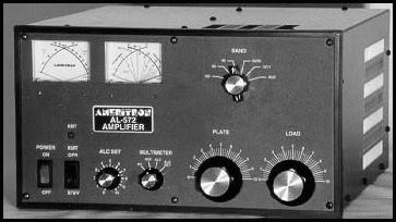 The Ameritron AL-572 Amplifier runs four (4) 572B tubes that produces 1200W CW. It has many features but one of the best
is its "Dynamic Bias Ckt" [DBC] that eliminates hundreds of watts of unnecessary heat generation
in the power amplifier tubes. The result is cooler operation and longer component life.
The Ameritron AL-572 Amplifier runs four (4) 572B tubes that produces 1200W CW. It has many features but one of the best
is its "Dynamic Bias Ckt" [DBC] that eliminates hundreds of watts of unnecessary heat generation
in the power amplifier tubes. The result is cooler operation and longer component life.Problem: As I've stated on the "Vox Mod" page, I really enjoy VOX operation but it's a bit 'hard' on my amplifier in that it forces the DBC to continually cycle. There are no "moving-parts" per se but the strain on the switching transistor makes it suseptible to a high voltage transient which can exceed the collector-to-emitter breakdown voltage [Vceo] causing it to suddenly "die"! Then the circuit reverts to a continuous bias mode so the static plate dissipation now takes over. About 450+ watts are wasted in heat and that, of course, raises the overall temperature level and, in some cases, may contribute to glowing red plates under a long SSB transmission. As you see in the comparison table, the high voltage switching transistor, Q103 has a 'breakdown' voltage, Vceo = 60V and is very suseptible to catastrophic failure for no apparent reason. When you transmit again (key down, no audio), you see quesient plate current with no RF drive signal, that's a sure sign that the transistor has failed. The table compares the parameters of the transistor. DBC Operation: Conventional bias circuits force high power linear amplifiers to dissipate hundreds of watts during low or no signal periods. This creates needless heat, since virtually no dissipation is required unless the amplifier is being driven with large signal levels. The AL-572 contains an exclusive bias circuit that reduces the idling (quiescent) current very close to the tube's cut-off region. The AL-572 power amplifier tubes have a full resting period of very low dissipation between dots and dashes on CW and between words on SSB. The lower idling current reduces component temperature on both CW and SSB. If only a few milliwatts of RF power are applied to the amplifier, the quiescent current will increase. Linearity remains excellent with this circuit because the tube can remain biased for class AB operation without unnecessary standing dissipation. The best of both worlds. The DBC is located on the Power Supply Board. Diodes D101 and D102 rectify a small sample of the RF drive voltage. This voltage is applied to the base of dc switching transistor, Q101. If Q101's base is driven with a few milliamperes of current from the RF sampling circuit, Q101's collector will pull the base of PNP transistor Q102 low. This turns the dc switching transistor, Q102 on. When Q102 is on, zener diode, D103 (9.1V zener voltage) is connected between the collector and base of Q103. D103 sets the operating bias. This zener applies forward bias to Q103's base whenever the collector voltage of Q103 exceeds the voltage of D103. This forward bias will turn Q103 on harder and reduces the collector voltage. If the collector voltage is less than the breakdown voltage of D103, Q103 will move towards cut-off and the collector voltage will increase. Q103 functions as a current buffer for zener diode D103. Check out the 5Spice transient analysis charts below. An improved part for this ckt is the "TIP122" darlington transistor. It features Vceo of 100V giving an added 40V safety margin. The second advantage is the "darlington" configuration is the added current gain meaning that less drive is needed to saturate Q103.
This section features a Spice ckt analysis run at 2Mhz. This frequency is "inside" of the Ham Radio Band allocation as it sits between 160M (1.8Mhz) and 80M (3.5Mhz) ham bands. The "period" of 2Mhz is 0.5us, so it's easy to use that time to construct an RF signal to be used as the stimulus input to the EBS ckt. Most Spice programs allow the construction of "piecewise" linear signal, as does 5Spice. This gives the user a powerful tool to use with Spice's "transient" analysis to completely characterize the ckt under test. A sample of the "text" file used to produce a 10 watt RF signal appear below. It is simply the time representation of the RF amplitude. The excerpt shows two (2) cycles of the 2Mhz waveform. A "text" editor can construct the file needed. *SSB_2Mhz@10Watts * *enter waveform data points *comment: first data point is at time = 0 *data format: *time amplitude 0.000u 0.0 0.125u 31.6 0.250u 0.0 0.375u -31.6 0.500u 0.0 0.625u 31.6 0.750u 0.0 0.875u -31.6 1.000u 0.0 At time "0", the amplitude is "0" volts; at 0.125us, the amplitude is 31.6 volts which represents 10 watts into 50 ohm load. The total duration of this test signal is 50us. This allows one to determine the sensitivity (gain) of the ckt along with its "turn-on" and "turn-off" time. All this with just one stimulus signal. Since the EBS ckt is supposed to respond to " . . milliwatts of signal" per W8JI, then 10 watts of RF drive should be overkill.
Stock DBC Ckt RF Analysis The stock DBC ckt schematic, after capturing into 5Spice, is shown below:   The chart shows the close-in detail of the RF signal applied to the stock EBS ckt. The "red" line represents the RF signal input; the
"blue" line represents the internal switch state; the "green" line represents the output of ckt.
The chart shows the close-in detail of the RF signal applied to the stock EBS ckt. The "red" line represents the RF signal input; the
"blue" line represents the internal switch state; the "green" line represents the output of ckt. Encouraging results! Carefully observe the "charging" action of the input signal (red) in relation to the output (green) chart line. The DBC ckt turns on in less than 10us and is fully 'settled' in 20us due to the very short time constants in the ckt. Also the output is 'clamped' by the zener diode (1N4739, D103) to 10V level. The output level remains clamped until 300us time point and then starts to slowly turn off. THis means the the AL572 amp is fully biased "on". The DBC ckt's response is excellent except that the HOLD time is a bit short for ESSB. A longer time, say 100ms would be more appropriate since an ESSB transmission has artifacts that are desirable to transmit WITHOUT distortion. To do this, you must have a longer hold time.  This chart shows the elapsed time up to 2ms. Note that the ckt's output is fully "unclamped" and the AL572 DBC ckt is "off". The DBC
bias ckt is fully off ( in "cutoff bias") at apx 2ms giving a usable "hang time" of apx 300us.
This chart shows the elapsed time up to 2ms. Note that the ckt's output is fully "unclamped" and the AL572 DBC ckt is "off". The DBC
bias ckt is fully off ( in "cutoff bias") at apx 2ms giving a usable "hang time" of apx 300us. This ckt operated very smoothly and not many, if any, "fixes" are required. Personally, the hang-time is a bit on the short side since most ESSBers have end effects such as reverberation so the hang-time s/b increased to 100 to 200ms. On the other hand, some do not use any effects, so the stock ckt would be to their liking. |
||||||||||||||||||||||||||||
|
Modified DBC Ckt RF Analysis The modified DBC ckt schematic, after capturing into 5Spice, is shown below: 
One such replacement is the TIP122. Its breakdown voltage is 100V and that makes it perfect for this application. It has much more current gain (hfe) and so the resistor, "Rswamp", 10K reduces some the current gain to prevent exceesive overdrive to the TIP122 darlington transistor. The clamp level for the stock ckt of 10 volts is OK as is and, although it could be fixed by replacing the 1N4739 zener with a lower breakdown zener such as the 1N4738 (8.5V), there is no need to do that. The operating bias is fine as is! The ckt hang-time can be improved by changing the value of R103, R104 and C106 from the stock values to the ones indicated in the "HOLD" time table. Making the indicated changes will increase the DBC ckt's hold time as indicated in the table. These parts will improve the DBC's operation and reliability of the Ameritron amplifier. In over 4 years of use, there's hasn't been a failure of the TIP122 so I recommend that you at least make this change.  The following charts show the detail of the RF signal applied to the modified DBC ckt. The "red" line represents the RF signal input; the
"blue" line represents the internal switch state; the "green" line represents the output of ckt.
The following charts show the detail of the RF signal applied to the modified DBC ckt. The "red" line represents the RF signal input; the
"blue" line represents the internal switch state; the "green" line represents the output of ckt. This chart shows the elapsed time up to 1ms. Note that the ckt's output is fully turned-on and clamped at 10V level by 40us and it's still fully clamped even at 1ms. This represents HOLD time table w/ R103, R104 = 220K and C106 = 0.22uF. At the 1ms time, the level of 10V meaning the AL572 tubes are fully biased "on" even after the input drive signal has been removed for 990us. |
||||||||||||||||||||||||||||
 This chart shows the elapsed time to 100ms with the R103, R104 = 220K and C106 = 0.22uf. Note that the output (green line) is still
"clamped" at the 10V zener level meaning the AL572 is fully biased "on". This time represents the total hang-time of 100ms. A
smooth operating EBS ckt with a decent hang-time for ESSB operation.
This chart shows the elapsed time to 100ms with the R103, R104 = 220K and C106 = 0.22uf. Note that the output (green line) is still
"clamped" at the 10V zener level meaning the AL572 is fully biased "on". This time represents the total hang-time of 100ms. A
smooth operating EBS ckt with a decent hang-time for ESSB operation. The DBC ckt also performed adequately with as little as 5Watts drive. Are these realistic inputs? On 75mtrs, I drive the AL-1500 with 20 watts from the FT-2000D, so my example using 10watts is meaningful. The stock DBC ckt performs very smoothly and, except for the shorter hang-time, there's no need to modify it except to change the output transistor (Q103) due to failure problems. The modified DBC ckt switches "on" (25us) almost instantly and exhibits a 100ms hang-time. As a "bias-power" saver ckt, it performs nicely almost independent on input drive power. As with all DBC and EBS ckts, the higher the input drive power, the better they perform. The modified DBC ckt works with 5 watts or greater input drive. At 5 watts drive, the turn-on time changes to 40us but all other parameters stay the same. The ckt improvements make the DBC ckt an already smoothly operating bias ckt for any linear with any operating mode even QSK CW. Note that it fully meets the requirements for a "fast" turn-on (20us) and "short" hang-time (300us) as design goals. The cost of the TIP122 replacement transistor is as low as . . . $0.61! For the increased HOLD time, it's as low as . . . $0.27! Parts Access: Transistor, Q103 is located on the wall divider between the power supply section and the tube compartment. The TIP122 is the same size (TO220) as the MJE3055 so the replacement is easy. When removing the MJE3055, make sure to save the mica washer and hardware to re-use it when mounting the TIP-122. That s/b obvious but have received email where some did not! If the mica washer is damaged during removal of the old transistor, click on the Mica Washer link to purchase a replacement. Thermal grease can be purchased at Mouser if needed. The "swamp" resistor is an "add-on" part that mounts on the ends of R107 and D103 or across the BASE and EMITTER leads of the TIP122. The modification should only take 15mins once the cover has been removed. Note that other than the Q103, nothing needs to be removed. All parts are on the Power Supply Board, PN 50-0080-1. Detailed Parts Info: These are common parts and can be found in most electronic stores. The best pricing can be had from Mouser Electronics. The last two (2) items have been included in case you can't re-use the mica washer and grease. Ref Des ----- Value ------ Price/Ea ------ Link ------- Remarks Q103 ------ TIP122 ------ $0.63 ------ -here- ------ 100 Vceo + high "beta"! Rswamp ----- 10K ohm ----- $0.23 ------ -here- ------ 10K ohm, 1% film resistor! R103,R104 -- 100K ohm ---- $0.23 ------ -here- ------ 100K ohm, 1% film resistor! R103,R104 -- 220K ohm ---- $0.23 ------ -here- ------ 220K ohm, 1% film resistor! C106 ------- 0.1uf ------- $0.40 ------ -here- ------ 0.1uF, 10% ceramic cap! C106 ------- 0.22uf ------ $0.48 ------ -here- ------ 0.22uF, 20% ceramic cap! TO-220 H/W for TIP122 (Q103) Grease ----- H/W -------- $9.75 ------ -here- ------ Thermal grease for TO-220 Mica Washer - H/W ------- $0.10 ------ -here- ------ Mica washer for TO-220 Comments: The Dynamic Bias Ckt (DBC) transistor + resistor mods described has been in use for 4 years and have proven to be reliable and has withstood all kinds of operator "mis-operation"! The original parts failed continually so this mod is a very reliable, rugged solution to the problem. And it's cheap! The HOLD time changes will guarantee a smooth, distortion free RF ESSB signal. The parts changes described make the ckt response guaranteed to pass an ESSB envelope with no distortion! Feedback from Scott, W1BBC: I performed your bias timing mod with the longest timing. I also dropped the zener voltage down. It performs excellent right down to 5 or less watts input with no fuzz in the audio. It now sounds as clean as my TL922A with ESSB audio. Thank you with your modification. It made it easy so I did not have to figure it out on my own. |
| Send me |