|
K6JRF's Page formerly W6FZC ESSB Audio Techniques Page |
|
This FT2000 Page discusses the techniques to attain clean ESSB (Extended SSB) audio
to 4Khz SSB BW in the 'ttbf' mode by exloring fundamental radio and audio characteristics required to produce this
audio along with how-to-do-this using both the radio's internal EQ plus external audio equipment. |
|
External Audio Equipment The next choice concerns the audio dynamics. The term 'dynamics' means all steps normally associated with processing of the audio signal. These are: gating, compression, limiting, de-essing and equalization. In order to more comprehend these, click on the many links in the aforementioned section. Take the time to read the details contained on these sites. It will help you understand the 'terminology' and give you ideas as to what is needed in your equipment lineup. The chart to the right shows my current audio system equipment and the "block" diagram shows all of the major interconnects between\ these equipments. The connections are standard and you will find that the interconnections shown will be required. Of course, these do change from time to time but the basic "ordering" concept has not changed. The numbers in blue at the top right side of each equipment, refer to the input impedance of the stage except for the microphone where this is its output impedance. The balanced interconnections are employed between all units using either XLR or TRS connectors except for the Alesis Microverb. If you aren't careful, you will get "hum" and that's indicates that you have a "ground-loop". The use of balanced interconnections (XLR) will ensure that these are minimized.  The output from the dBX DDP is balanced and is transformed in the Ebtech isolator to unbalanced to match the FT2000 mic input
connection. One channel of the Ebtech Hum Eliminator
is used to ensure a ground loop free connection.
The second channel is used for the Sony E10 MDS playback EQ, ensuring complete isolation between the audio processing system and
the FT2000.
The output from the dBX DDP is balanced and is transformed in the Ebtech isolator to unbalanced to match the FT2000 mic input
connection. One channel of the Ebtech Hum Eliminator
is used to ensure a ground loop free connection.
The second channel is used for the Sony E10 MDS playback EQ, ensuring complete isolation between the audio processing system and
the FT2000.Audio Equipment Hierarchy I firmly believe that the 'cleanest' sound is produced by; 1) attenuating any 'unwanted' frequencies before they enter the main processing chain, 2) using equalization (DEQ2496) processing ahead of any Gating, Compression and De-essing (or Limiting), 3) always adding reverberation effects as the last piece of equipment (if you use reverb; I do not use it any longer). Therefore the my audio processing system reflects this philosophy. 1) For my voice, '160hz' is a no-no. Thus the Behringer MIC2200 preamp's EQ stage is used to remove this frequency before it enters the processing. 2) The Behringer's Ultra Curve DEQ2496 is placed in front of the dBx DDP, Digital Dynamics Processor. This gives the DDP's compressor, limiter and de-esser the ability to compress, limit and de-ess the audio signal so that there is no chance of overdrive, harshness or clipping to the audio signal that drives the mic input of the FT2000. 3) The Alesis MicroVerb III which was at the end of the chain has been removed. The reverb effects are not normally heard unless signals are S9 + 30db or more so this function is mostly useless. However, if you use one, it should be at the end of the chain since if a Gate is used, it will close very quickly so the reverberation effect is 'cutoff'. If you make the Gate unaturally long, you are defeating the reason for the gate! |
||||||||||||||||||||||||||||||||||||||||||||||||||||||||||||||||||||||||||||||||||||||||||||||||||||||||||||||||||||||||||||||||||||||||||||||||||||
Real ESSB Example In order to see what's involved, what's better than a picture. These are spectrum plots made with SpectraPlus, a software program that turns your computer's sound card into a low frequency spectrum analyzer. The picture below shows the transmit audio response of my former radio, FT1000D taken by VE6CQ. The Tx bw is basically flat from 50hz to 3.1Khz. The key is the balance that it possess. The difference from top to bottom is less than 3dB - 4dB. Also the mid range frequencies are slightly attenuated so as to bring out the resonant bottom and top frequencies, where the 'articulation' lies. FT2000 Internal Menus Settings The following sections are specific to the FT2000 radio and show my current alignments and adjustments along with the external audio equipment and its settings. Unlike my former FT-1000D that required "manual" adjustments inside the radio, most of the FT2000 adjustments can be made via the menus accessible from the front panel! This truly makes it very much easier to adjust the radio's parameters.
* the "low" [EQ1], "mid" [EQ2] and "high" [EQ3] EQ ranges should be set at shown. If so, you can be assured that the
Tx BW is flat from 50hz to 4Khz as shown in the white noise Tx sweep chart below.
This section shows the FT2000 no-EQ response in either Rx or Tx modes!. This discovery has made it quite easy to 'flatten' the radio's response from 50hz to 4Khz with just one (1) EQ curve resident in the DEQ2496 and DDP. Using WWV @ 10Mhz, the following chart was made using SpectraPlus. It's the raw response from the FT2000 in 'ttbf' mode.
On the hardware side, this may be possible to 'fix' by replacing a 'capacitor'. This was done during the FT1000 re-design effort. Hopefully, the same thing may happen as I start to dig into the FT2000 schematics. Until that is accomplished, the PHONES jack output is not very useful b/c of the extreme frequency response rolloff. The green chart shows first corrected response in the DEQ2496. Note that it's essentially flat and all recordings sent to either the computer or MiniDisc (MD) are recorded with a flat response. Note that when it's re-transmitted additional EQ is needed to compensate for the Tx BW rolloff. Once done, the re-transmitted "copy" of the original signal will be identical to the way it was received. Can't ask for anything better! The "block-diagram" interconnection sketch shows the details of how-to-do-this. For Rx, this is accomplished by use of the DEQ2496. The red chart shows the extremely flat response generated by the DDP during "playback". It's as flat as flat can be! A ESSB signal playback is indistinguishable from the original. For Tx, this is accomplished by use of the DDP. The main settings for Rx and Tx BW measurements are: IPO = ON, RFLT = 15Khz; VRF = OFF; Width = Max. Receiving and/ or recording ESSB signals s/b use these settings. This will guarantee the maximum response from the radio. FT2000 Playback EQ Sweep Tests - "Flat Response" Most ESSB enthusiaists have the capability to capture Tx audio, display its BW using SpectraPlus (or similiar) and finally, play it back to you as a faithful reproduction of what was captured. This latter function requires that your radio's playback capability be compensated to be 'flat'. Not all radios have the same playback BW; the FT2000 captures the signal from 50hz to 4Khz and can playback from 50hz to 4Khz. That's where the brick wall formed by the DSP third stage "IF" sets in . However, even with that minor limitation, the EQ must be adjusted to be flat. To that end, the chart shows the FT2000 playback response after using the dbx DDP's channe1 for the (see block diagram) EQ. 
The DEQ2496 has 31 and the DDP has 3 stages of parametric EQ that can be employed. The values for the center frequency, bandwidth (BW) or "Q" plus the level (in dB) are shown that flatten the FT2000's playback response. Properly EQing for a 4Khz Tx BW is different than for a 3Khz BW. One realization is that b/c of the higher upper frequency repsonse, the low-frequency response must be increased to 'balance' the sound. It's ok to have a slight favoring of the hi-freqs since it will make the sound brighter which is always a good thing. This section shows the EQ for the FT200's "TTBF" mode. This represents 50hz to 4Khz Tx BW. After all this time, I decided to see if the EQ has changed over the years. The MIC2200 preamp died and was replaced so time to check the settings and improve the present ESSB Tx audio. 
The three (3) sweeps show the details: The AQUA colored trace is the reference showing the flatness from 50hz to 4Khz. Using that as the starting point, the BLUE colored sweep shows the MIC2200 preamp response to the settings. The RED colored trace shows the total response using the MIC2200, DEQ2496 and dBx DDP processors. It's instructive to perform a Freq Sweep [FS] employing sinewave generated from the Utilities Menu in SpectraPlus Pro. To than end, I constructed a 50hz to 5000hz sinewave sweep with the sweep duration of 30secs. This was recorded on my Sony MD MZ55 and used as a signal generator. 
The GREEN chart shows the direct sweep response with no EQ to the FT2000D radio via the front panel MIC connector driven from the "Full Rack" in bypass mode. It shows a relatively flat response to 4Khz where the DSP forms a TX "brick wall". The BLUE chart shows the same sweep with the MIC2200 Preamp activated. This curve is almost identical to the GREEN chart except for the dip at 151hz from the one-stage EQ set to attenuate 151hz. The RED chart shows the response employing the "full rack" (MIC2200+DEQ2496+DDP) all processors active. The response at 60hz is attenuated by -9dB; at 151hz, -25dB; at 951hz, -30dB; at 2.5khz, +3dB. So the EQ is now verified using SINEWAVEs instead of white noise. The ESSB TX audio has low BASS smoothness and articulation with the rising HI FREQ response. The MP3 below was recored by Duke, NA1A using a FTdx9000 on 75mtrs. A little band noise but you get the idea! 
The SP chart made from an MP3 file captured by NA1A shows that it extends to 4Khz as is the "TTBF" mode. The mid-section is basically flat from 200hz to 3.8Khz and drops in level to 4Khz at the DSP's cutoff frequency. 
The EQ was born by capturing my voice via the TLM-103 w/ no EQ onto a Mini Disk. The recording was then captured by SP and a "raw" chart emerged. From this the "bad" spots were attenuated where needed including the low-mids. Only areas that needed EQ were 'touched' to remove "peaks". The high frequency area needed some added gain at 2550hz.
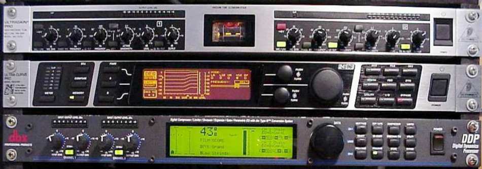
Audio Dynamics Processors and Settings: As you have seen, my current goal to minimize the use of external equipment so as to produce a more natural sound. As a consquence three (3) audio dynamics boxes have been removed and the "rack" repacked to contain all of my current "audio" devices. This section details the current ones in use along w/ their strong points. At the end the current settings are shown for each. 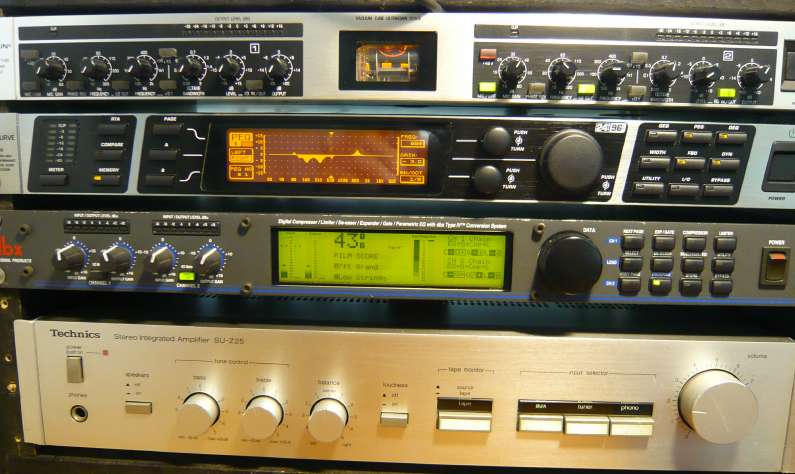 A key box that will never (??) be replaced is the "preamp". It's the top box in the photo above. The current one is the Behringer UltraGain 2200. It contains a tube ("GT" Electronics) preamp that produces a warm sound. The main advantage is a one stage parametric (boxed in red) EQ that allows full control of the mic's input signal and pre-processes any frequency from 20hz to 10Khz with "attenuation" or "gain". I use it to remove the heavier low-mid frequency range (150hz to 300hz) BEFORE it gets into the following stages. 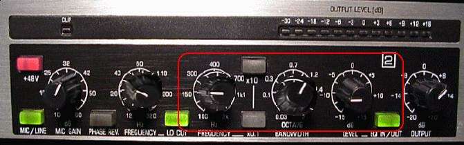 DEQ2496 Ultra Curve: The single replacement for the removed audio dynamics processors is the Behringer DEQ2496. It's the second box down from the top in the photo above. This is now my primary audio processor and I can say that it's a marvelous piece of DSP hardware and software. It tailors the audio dynamics not only based on "frequency" but also "level", so the EQ can change as a function of the input signal level! It can raise or lower the level of a specific frequency (or a band of frequencies) based on two parameters, "Gain" and "Threshold". Other parameters control the speed of how this is done. The standard usage of this device is to "lower" the gain above a certain level however many are not aware of another way of using the DEQ processor. That is to use it to "RAISE" the level rather than lower it. It has some advantages that would be hard to accomplish with a 'standard' audio dynamics equipment over a wide frequency band.  An example shows how this happens. Setting the "M-Gain" to a positive number (+10dB) means that as soon as the level drops
BELOW the "Threshold" (-23dB), the gain is increased by the amount of the M-Gain number, 10dB. When the input signal
level goes above the "Threshold", it is reduced by -10db to the "normal" value. The results are a louder audio almost
as if it was 'compressed' for low (soft) mic input levels.
An example shows how this happens. Setting the "M-Gain" to a positive number (+10dB) means that as soon as the level drops
BELOW the "Threshold" (-23dB), the gain is increased by the amount of the M-Gain number, 10dB. When the input signal
level goes above the "Threshold", it is reduced by -10db to the "normal" value. The results are a louder audio almost
as if it was 'compressed' for low (soft) mic input levels. Another way is take advantage of the DEQ's power is to use the shelving filter, "H12" (high-pass, 12dB/oct) or the "L12" (low-pass, 12dB/oct) rather than the bandpass filter, "BP". This results in a larger region of controlled gain audio.  In DEQ #1, the H12 shelving filter attenuates all frequencies above 100hz. In DEQ#3 as shown on the right, the L12
shelving filter results in all frequencies below 2000hz being attenuated when signal level crosses the threshold level.
This is a novel way of damping frequencies across a large frequency spectrum, 50hz to 2000hz.
In DEQ #1, the H12 shelving filter attenuates all frequencies above 100hz. In DEQ#3 as shown on the right, the L12
shelving filter results in all frequencies below 2000hz being attenuated when signal level crosses the threshold level.
This is a novel way of damping frequencies across a large frequency spectrum, 50hz to 2000hz. Currently using the H12 settings for DEQ #1(Lo Freq) and DEQ #3 (Hi Freq). DEQ#2 (Mid Freq) uses the BP function. Check out my "Current Audio Settings" table below. Try them, they should at least get your SSB audio into the ballpark. dbX Digital Dynamics Processor (DDP): My seccondary processor is the DDP. This is the third box down from the top in the above photo. This is an excellent DP and there's no plans to replace or remove it. It has the necessary audio dynamics functions such as Gate, Equalizer, Compressor and Limiter. Currently, just the Gate and Compressor are being used. The DDP is a DSP device and it has an extremely clean response with no audio coloration which is key for any good audio dynamics processor.
Current Dynamics Settings: The table above shows my current audio dynamics settings for easy reference. As you see, all settings are changed regularly b/c there are no "sacred" positions. These settings may need to be 'tweaked' abit for your particular radio and microphone but they should get you in the ballpark. here that is reflected in the DEQ2496 settings below.
[Current Audio Settings for FT2000D: 04/15/20] In the dBx DDP, EQ is running in the "Bright" mode to add sparkle. The LIMITER provides a 'clamp' that actually limits the drive signal without clipping the signal. That allows it to generate in-your-face sounding ESSB audio w/o overdriving the FT-2000D input.
Note: The settings here are for use with the "Full_Rack_EQ". Make sure to turn OFF the radio's EQ settings. Check back regularly for the latest updates.
|
 An excerpt from the "FT2000 Rx & Tx White Noise Sweep - TTBF" shows the extreme rolloff from the FT2000's PHONE
jack output [2nd BLUE line] of -18.5dB @ 4Khz! Obviously not useable. This
section shows how to generate the compensation file that will correct for lack of flatness.
An excerpt from the "FT2000 Rx & Tx White Noise Sweep - TTBF" shows the extreme rolloff from the FT2000's PHONE
jack output [2nd BLUE line] of -18.5dB @ 4Khz! Obviously not useable. This
section shows how to generate the compensation file that will correct for lack of flatness. 

|
Send me |