|
K6JRF's Page formerly W6FZC FT1000D Balanced Modulator (BM) Page |
|
This BM Page details the required modifications needed to the FT1000D to allow
external audio signals to directly drive the balanced modulator without the audio shaping normally attached to the
FT1000D's audio preamp stages.
Note 4 details all of this. The detailed 'how-to-do' instructions for the BM cuts and jumpers are contained in the Schematic Diagram plot in the BM RESULTS section. |
|
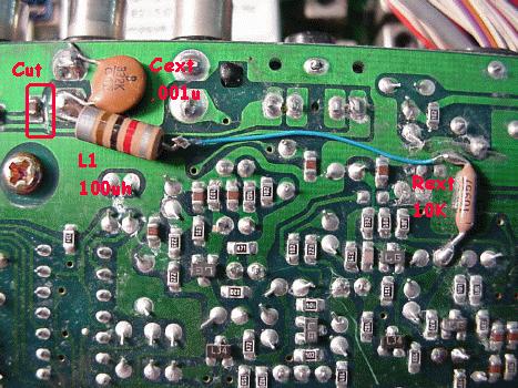
NOTE 4 This note details changes to the FT1000D for direct drive of the BALANCED MODULATOR (BM). Also a novel method of bandwidth verification and alignment using pink noise is explained.This change allows you to directly access the balanced modulator (BM) in the FT1000D so that you can directly modulate the transmitter without any other changes to the radio or use the internal audio stages. Note, however, that this will NOT give you wb audio without performing the TCP adjustments and adding the wider InRad filters. You can however, drive it with external equalization to make up from the loss in frequency response to obtain very clean audio. I made this mod to the radio some time ago when I was experimenting with 'better' methods of obtaining wb audio but quickly abandoned this method because of loss of VOX operation! My VOX changes described in later notes, make the radio a joy to operate and losing VOX made it too much of a burden! I do use it now for the playback of taped audio. Using the BM drive precludes VOX operation since the VOX pickoff point occurs in the 2nd last stage transistor Q3080 in the audio stage. Transistor Q3032 is the audio buffer output that drives the BM (Q3031) input. Referring to the schematic below, the mods are marked in RED. Note that this is the same ckt as attached in Note 2, but that the BM changes are now shown in the red 'box'. This ckt has been re-simulated to include the effects of the BM direct drive. Note that the load (Rl) that originally was assumed to be 1K ohms is lower. Subsequent testing showed that the load is somewhere around 220 ohms minimum to around 800 ohms maximum. Assuming the worst case, around 330 ohms (220 ohms for R3127 plus 100 ohms for the BM input) gives the NEW value circuit simulation resulting in a change in value for C3123 (22uf). Subsequent testing seems to bear this assumption out. Referring to the first picture in the BM RESULTS sectiopn, we see that a pink noise (PN) sweep of the BM ckt shows that the response cuts off around 200hz. Remember that a PN sweep is flat if the drop is 3dB per octave. Below 200hz the drop per octave (i.e. 200hz to 100hz) is around 9dB. All charts were plotted using SpectraPlus (SP). This site gives you pertinent info if you are interested. The PN generator is also derived from SP to do the Tx alignment. I use SP in conjunction with a laptop to form a mobile alignment and calibration tool. The use of pink noise results in a time saving, accurate method of aligning any signal path assuring a flat frequency response. The spice circuit analysis was performed using PSPICE which is available from OrCad Corporation. Analysis: The additional ckt components added are shown in the picture below and in the RED box of the schematic. Specifically these are L1, 100uh; Rext, 10k; Cext, 0.001uf; C3123, 22uf. L1 and Cext are mandatory! They insure that the circuit is RFI proof! These were added recently when RF intermittently became a problem. The BM input is the EXT ALC jack, J3002-2 which was modified by insertion of a CUT on the underside of the AF UNIT Board. If need be, this cut can be repaired very easily to return the radio to stock condition. AF UNIT Board: The following instructions are for adding the additional BM components to the under side of the AF UNIT Board. The removal and preparation of the AF UNIT Board is described below in the schematic, FTaud3a.gif. You will need an FT1000 Service Manual and be proficient at un-soldering to accomplish this change!
2) Remove C3123, 4.7uf, 35V capacitor. Replace it with a Radio Shack 276-1026 22uf, 35V cap. 3) Solder Cext, 0.001uf disk (Radio Shack 272-126) ceramic cap from the center post to the ground post of C3002-2. 4) Add a jumper wire from the center conductor of C3002-2 with the following components in series: L1, 100uh and Rext 10k, 1/8w resistor to the junction of R3292 (10k) and C3124 (4.7uf). Refer to the FT1000 Service Manual to locate these parts. Dress the part carefully and make sure that they do not short to circuit pads or component leads from the other side of the board. 5) Clean up the solder, reinstall the AF UNIT Board and both covers. There is no alignment necessary for this modification. |
|
BM Results The results of the BM addition is shown here. Note that a cut and jumper is needed to add this enhancement.
Referring to picture below for the BEFORE and AFTER results. The RED line in the chart represents a pink noise sweep through the BM before the C3123 change (4.7uf). SpectraPlus's pink noise signal was recorded onto a Sony Minidisk recorder (MZ-R55) directly from the laptop. Then this 'audio' signal was inputted into the now converted EXT ALC jack as the source signal to drive the BM. The response was recorded by using the phone jack output signal into the SP program running on the laptop. Note that the low frequency response falls off around 200hz to 250hz. This can be changed by moving the TCP adjustment lower in frequency but I chose to leave it alone since I chose the higher TCP adjustment to give the highest frequency response possible. At low frequencies, it's easier to add it back in as needed via external equalization with the DDP or Aphex 104. The AQUA line represents the result of the playback through the FT1000D with the C3123 cap change (22uf) and equalization via the dBx Pro DDP unit. The values are shown in the file. Note that the bandwidth is now flat from 70hz to 3Khz.
The change results in extended bandwidth and sonically accurate audio playbacks from minidisk media through the FT1000D. |
|
Send me |