|
K6JRF's Page formerly W6FZC Collins Mechanical 455Khz Filters |
|
This page documents the testing of Collins mechanical filters as a more
optimum replacement for either the InRad #715 filter or the Murata CFS455F ceramic filter. Here
'optimum' means the ability produce the widest transmit audio bandwidth when a fixed 2.9Khz filter
(InRad #716) is in the 8.2Mhz IF. |
|
Introduction: The FT1000D employs two filters on receive and transmit; one in the 8.2Mhz IF and the other in the 455Khz IF. The stock filters are 2.6Khz wide producing about 2.4Khz overall bandwidth. In general, when two filters of equal bandwidth are cascaded, the resulting bw is always less than the individual filters bandwidth. Thus in order get get the widest possible bandwidth (for both transmit and receive), you must make the lower IF filter have a greater bandwidth so the limiting factor is the first filter in the 8.2Mhz IF. Of course, you can make the higher IF filter have greater bw but now anything over 3.0Khz gives problems with opposite sideband suppression. Discussion: Today as I was looking at the electrical diagram of the Murata CFS455F filter an important fact, heretofore missed, was clearly evident. If you look carefully at the skirts around the -6dB point you see that the filter becomes much more lossy at these points than at the center frequency, about 6dB on the low side and 3dB on the high side.
Note that the CMF's group delay is an order of magniture less (50us vs 400us) than the Murata ceramic filter. This means that the audio spectrum is more coherent (less time difference between low frequencies to high frequencies) than is with a Murata.
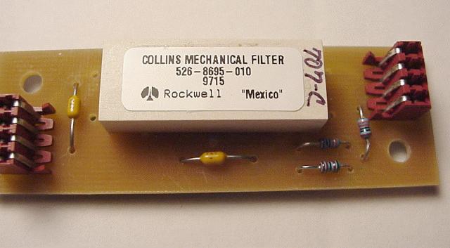
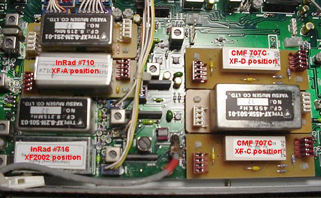
So in order to test this theory, I ordered two '707C' filters for the '2.0K' and '2.4K' positions in the FT1000D. The 'C' means that the CMF is mounted on an InRad 101 style board which is designed to plug into the FT1000D. This picture shows a CMF ready to install into the radio.
Info on the InRad crystal filter; '716B' Info on the Collins mechanical filter; InRad '707S' Info on the Murata ceramic filter; 'Filter has been discontinued and data removed' Present FT1000D Filters The plot below shows results of using a sine wave sweep for the 'Tx' tests and WWV at 10Mhz for 'Rx' tests. The plots show the results of the presently installed filters in my FT1000D. The Tx stimulus source consists of my Sony minidisk with a pre-recorded version of a 30hz to 5Khz sine wave sweep with 60 secs duration. The Rx signal source was WWV at 10Mhz. The results were recorded using my laptop computer with SpectraPlus as the spectrum analyzer. Tx Tests: Using the Tx stimulus, the FT1000D was swept using both the '2.0K' and '2.4K' positions. In my radio the '2.0K' is my wideband position: a InRad #710 (6Khz @ 8.2Mhz) and Murata CFS455F (+/-6Khz @ 455Khz). In the '2.4K' position, the filters are: InRad #716 (2.9Khz) and Murata CFS455F. The radio transmits in '3Khz' and receives in either '3Khz' or '6Khz'. The RED and PURPLE trace show the response with no equalization and with full equalization respectively. The lower frequencies are boosted by about 5dB while the upper frequencies are boosted by about 1dB. Rx Tests: Using the Rx stimulus the rig is placed into 'LSB' mode. Then using the FT1000D's 'RX' [receiver offset] function, a slow sweep from zero-beat up through 6Khz is repeated several times until it pattern averages out to what you see. The BLUE (6Khz) and AQUA (3Khz) traces show the results of '6K' and '3K' filters respectively. Here we graphically see the difference between the two filter banks. The '3Khz' has the same response from 200hz to 3Khz but it falls off rapidly below 200hz. For example, at 100hz the difference is about 10dB.
|
|
Collins Filter Results The results of the testing were as expected by not to the degree experienced! The CMF graphs (in yellow) show a very smooth response for both the '2.0K' and '2.4K' position with lower insertion loss and, most important, wider bandwidth than the Murata filters.
In summary, the Collins mechanical filters show as much smoother and have less insertion loss compared to the Murata filters. To Murata's credit, they provide acceptable performance plus they were obtained 'free'! However, the 'drooping' bandpass characteristic due to low 'Q' makes them less useful for wb audio work. |
|
Send me |