Fault Table, DTC Readout, ABS w/ASR Control module (N30/1)
Socket 1: Black (ground)
Socket 3: Red (12V)
Socket 6: Yellow (ABS/ASR output)
| DTC |
Possible Cause |
| 1 |
No faults in system |
| 2 |
Left front axle vehicle speed sensor (L6/1) |
| 3 |
Right front axle vehicle speed sensor (L6/2) |
| 4 |
Left rear axle vehicle speed sensor (L6/3) |
| 5 |
Right rear axle vehicle speed sensor (L6/4) |
| 6 |
Left front axle solenoid valve (A7/3y1) |
| 7 |
Right front axle solenoid valve (A7/3y2) |
| 8 |
Left rear axle solenoid valve (A7/3y3) |
| 9 |
Right rear axle solenoid valve (A7/3y4) |
| 10 |
Return/pressure pump relay (A7/3k2), return/pressure pump motor (A7/3m1) |
| 11 |
Solenoid valve relay (A7/3k1) |
| 12 |
MODELS 140.04/05: Master cylinder switchover valve (Y61) |
| 13 |
Stop Lamp switch (ASD/ASR) |
| 14 |
MODELS 140.04/05: ABS lateral acceleration sensor (B24/2) |
| 15 |
ABS/ASR control module (N30/1) |
| 16 |
Vehicle speed sensors (L6/1, L6/2, L6/3, L6/4), wrong, dirty or damaged toothed rotor) |
| 17 |
Low voltage at solenoid valve relay (A7/3k1) |
| 20 |
Switched/solenoid valve (A7/3y5) |
| 21 |
Pressure switch (A7/3s1) charge |
| 22 |
Pressure switch (A7/3s1) leakage |
| 23 |
Pressure switch (A7/3s1) hydraulic system |
| 24 |
ASR charging pump (M15) |
| 30 |
CAN data line to EA/CC/ISC module (N4/1) |
| 31 |
CAN data line to: LH-SFI control module (N3/1)
left LH-SFI control module (N3/2)
right LH-SFI control module (N3/3) |
| 32 |
CAN data line to: left ignition control module (N1/4)
right ignition control module (N1/5)
ignition control module on LH-SFI (N1/3) |
| 33 |
CAN data line, short/open circuit |

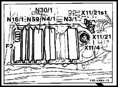 The ABS control unit (N30/1) receives input from the four (4) wheel sensors, stop lamp switch, electronic accelerator unit,
snow chain switch, and pressure reservoir switch. The ABS control unit turns these input signals into output control signals
for the following components; hydraulic unit solenoid valves, relays (solenoid valves, return/pressure pump, and ASR charging
pump), electronic acceleration control unit, ASR indicator lamp, snow chain switch LED, ABS warning lamp and ASR warning lamp.
From the input signals, the ABS control unit differentiates between three (3) operational modes; normal operation, ABS
operation and ASR operation.
The ABS control unit (N30/1) receives input from the four (4) wheel sensors, stop lamp switch, electronic accelerator unit,
snow chain switch, and pressure reservoir switch. The ABS control unit turns these input signals into output control signals
for the following components; hydraulic unit solenoid valves, relays (solenoid valves, return/pressure pump, and ASR charging
pump), electronic acceleration control unit, ASR indicator lamp, snow chain switch LED, ABS warning lamp and ASR warning lamp.
From the input signals, the ABS control unit differentiates between three (3) operational modes; normal operation, ABS
operation and ASR operation.