|
Diagnostic Connectors, Controller Area Network and Scan Tools
Diagnostic Connectors X11/4 and X11/21
 The standard diagnostic test point for all W140 autos is the X11/4, 38 pin connector located in the F23 module box in the
right rear portion of the engine compartment. The module box is closed and air cooled by a blower motor (phased out at end
of '95 model year). The cap which allows access to X11/4 contains a rubber gasket to prevent warm engine air and water
entry. Note the auxiliary Diagnostic X11/21 switch with LED for local DTC readout of the DIAGNOSTIC
MODULE (N59) only.
The standard diagnostic test point for all W140 autos is the X11/4, 38 pin connector located in the F23 module box in the
right rear portion of the engine compartment. The module box is closed and air cooled by a blower motor (phased out at end
of '95 model year). The cap which allows access to X11/4 contains a rubber gasket to prevent warm engine air and water
entry. Note the auxiliary Diagnostic X11/21 switch with LED for local DTC readout of the DIAGNOSTIC
MODULE (N59) only.
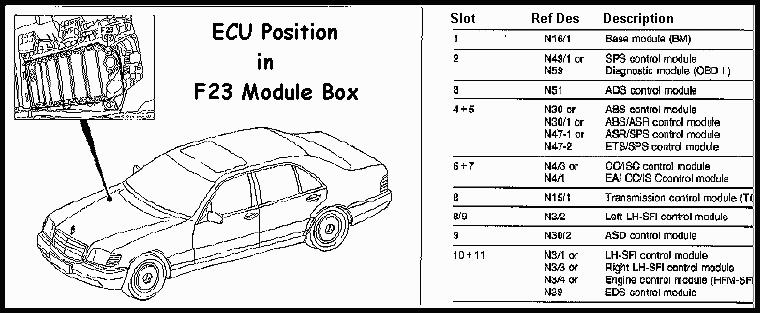
The five (5) ECUs in the F23 box are (California):
N16/1 = Base Module
N59 = Diagnostic Module (California)
N4/1 = Electronic Accelerator/Cruise Control/Idle Speed Control Module
N30/1 = ABS/ASR [AntiLock Brake System/Anti Slip Control] Module
N3/1 = LH-SFI (Sequential Fuel Injection) Module
The picture below shows all possible combinations of ECUs for both California and Federal version vehicles.
 Read Stored Codes from X11
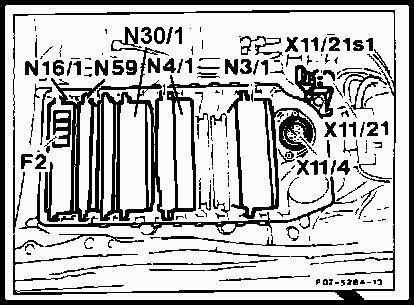
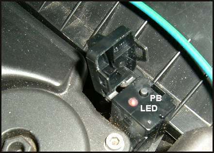
To read out DTCs from the Diagnostic Module (N59), locate the X11/21s1 switch as shown in the picture. Remove the protective
snap cap exposing a LED and PUSBUTTON. Turn the IGNITION to ON making sure that all display lamps are illuminated. Press the
PB for apx 5 seconds. If there are no faults in the system, the LED will flash once indicating no faults stored in the system.
Any number of 'flashes' greater than one indicates the DTC stored in the system. Unfortunately, this great user friendly
feature was discontinued at the end of the 1994 model year.
Press the PB again for apx 5 seconds. If there are further faults in the system, the respective DTC will be displayed. If
there no additional faults, the previous DTC will reappear. Repeat this step until the first DTC is displayed. Note all faults
by writing them down.
|
|
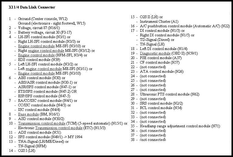
X11/4 Pin Map
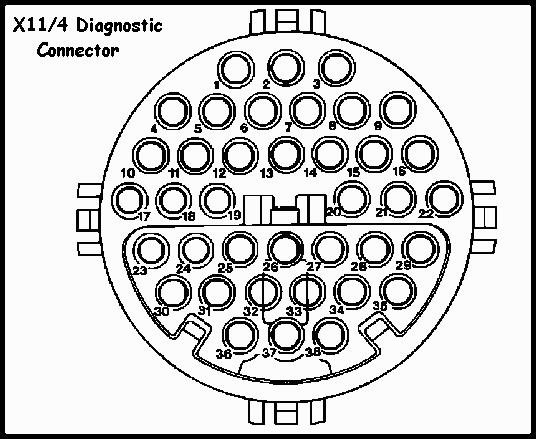
ECU Connection Pins of Diag Connector X11/4
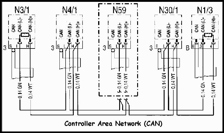
Controller Area Network
The controller area network (CAN) connects all ECUs together electrically so information can be transmitted from one
control module to the others. This exchange network results in more information for the control modules, less wiring and
lower vehicle weight.
Purpose
The Diagnostic module (N59) monitors the engine control systems and their ECU's to assist the technician during the check/
troubleshooting process. If the module detects a system/component malfunction, it illuminates the 'CHECK ENGINE' light in
the instrument panel.
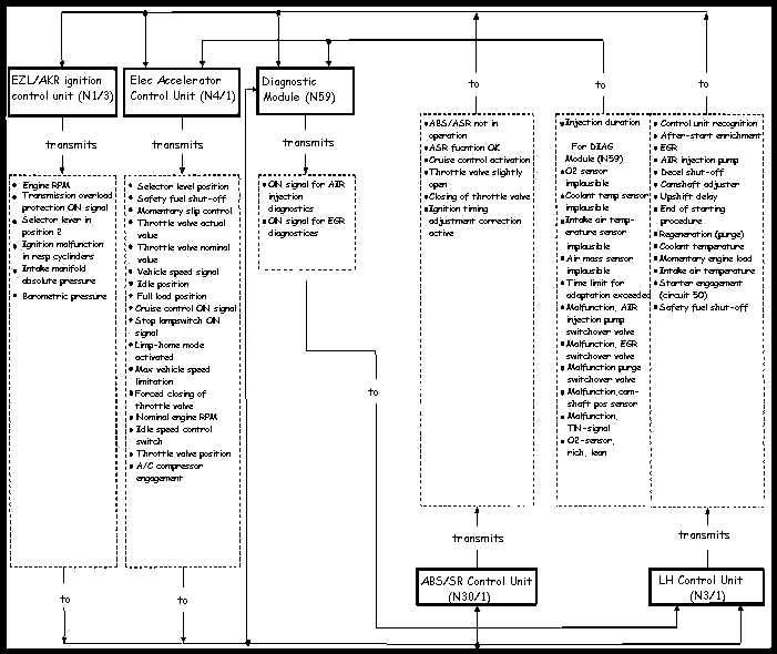
The diagram below shows the interconnection of the five (5) major ECUs (black boxes) and controlling/system monitoring
produced by each module. The CAN bus ties all of the ECUs together. All faults are stored in the DIAG module for
convenience (California cars only.)
DTC Fault Levels
Some ECUs have multiple levels of fault storage. These are called 'Active', 'Registered' and 'Stored'. Here's what they
mean.
Active Faults - These faults are detected while the car is running at idle or speed. They represent a component
that may be or is currently failing. These codes cannot be erased. They are only meaningful with the ignition on and the
engine running so DTCs found in this system with the "key-on-engine-off" usually have no meaning. Sometimes it shows a
components not present on the car as failing so these codes do more to confuse than to serve as a diagnostic tool. But if
the code persists, and the CEL lights, then it indicates a bad component but not necessarily the DTC that's stated!!! Thus
the confustion.
Registered Faults - These faults are recorded in the temporary memory of the of the car's ECUs. This temporary memory
records the the fault indicating that it has occurred and is continuing to occur but it hasn't exceed the preset number of
times to make it a Stored fault. When that certain number of failures has occurred, the fault is now moved to permanent
(Stored) memory and the CEL lights. Some ECUs that have internal fault registers, the CEL may stay on after the Stored or
Permanent fault has been erased if another occurrence of the fault has happened since the 'permanent' fault was stored. To
extinguish the CEL, you should always erase both Stored and Registered faults after fixing the faults indicated.
Stored Faults - These DTCs are sometimes called 'permanent' codes. When that preset number of failures has occurred,
the fault is now moved to permanent (Stored) memory and the CEL lights. These faults are recorded in the ECU's permanent
memory and are the main cause of CEL light. They have been generated because the fault exceeded the preset number of times
set up for for that function. These DTCs can (and should) be erased after the fault is fixed.
Erasing DTC Memory
After eliminating a fault, the respective DTC readout must be cleared as follows: Press the PB for apx 5 seconds and read
out the DTC. Then within 10 secs, press the PB for apx 9 seconds. Then turn the ignition off for 15 secs. Note the EACH DTC
must be cleared INDIVIDUALLY! If the fault has been eliminated and its respective readout erased, the DTC will no longer be
displayed when performing DTC readout.
DTC Readout
To read out DTCs, locate the X11/4 connector near the right rear side of the engine compartment. Remove the protective cover
exposing a 38 pin connector. Plug the mushroom adapter to give access to the 38 pins based on the ECU being tested. Plug in
the three wire leads (Red, Black, Yellow) to the pins referenced for each DTC chart in the Main Menu above. This powers
up the Pointer Scan tool and prepares you to perform the DTC readout.
Now turn the IGNITION to ON making sure that all display lamps are illuminated. Then push the Enter key to cycle the program.
A display of 'No Faults' means the system is clean! Additional faults are displayed by pressing the UP key. All faults
are displayed in plain English on the LCD screen rather than the actual DTC itself. Repeat this step until the first DTC is
displayed. Note all faults by writing them down. After repair of each fault, repeat the above procedure but this time select
'RESET FAULTS' from the menu. Completing this action clears all DTC codes from the selected module's memory.
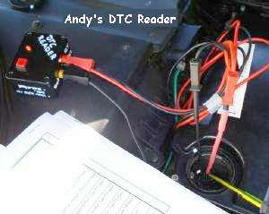
Home Brew DTC Tool
 You can build a very handy DTC reader from parts available at Mouser Electronics. This simple tool allows you to read
DTCs from the car without having to spending a large sum of money for a scanner. This tool can be built for under $15. Cost of
all parts detailed below is under $12.00. Parts that are stocked by Mouser are shown in BLUE for
your convenience. Of course you can use a multiplicity of other parts.
You can build a very handy DTC reader from parts available at Mouser Electronics. This simple tool allows you to read
DTCs from the car without having to spending a large sum of money for a scanner. This tool can be built for under $15. Cost of
all parts detailed below is under $12.00. Parts that are stocked by Mouser are shown in BLUE for
your convenience. Of course you can use a multiplicity of other parts.
Click on the links [here] to see the technical specs and pricing for each part.
LED:
Add a 470 ohm-1/4W resistor in series with the + lead if you don't have one with an internal resistor. This one
has an internal resistor -
here
Momentary SW:
Any SPST switch will work but it s/b momentary -
here
Banana Plug:
Any pre-made cable with red, black or yellow plugs can be used. Cut the cable leaving enough to solder to ckt point.
RED -
here
BLACK -
here
YELLOW -
here
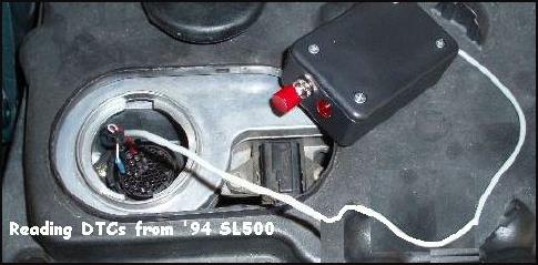
Some Mercedes (W140, C140) that have the X11/4 connector require small male pins to plug into the female X11/4 pins. You will need three
(3) pins to replace the banana plugs. Check the pictures below showing two (2) methods of making contact. Personally, I prefer the use of
the male pins shown in the right ['94 SL 500] picture. Mouser stocks pins that are suitable -
here
Fuse:
A low power (less than 1amp) will also work -
here
Box:
Any plastic box will work nicely as long as the parts can fit -
here
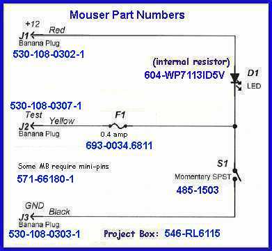
The only drawback: You still need a reference document to see what the LED flashes mean. But that can be done, so here's the
schematic of the Code Reader. Note that this unit works for all MBs with ANALOG systems, ie most
cars up to and including 1993. Also some 1994 systems were mixed, both analog and digital.
|
After you build the scan tool, you'll need a DTC Manual to show what the 'blinks' mean!
Click here to show the W140 DTCs for the Diagnostic Module (N59).
Use a Scan Tool
Although not currently being made, the Pointer Scan Tool is an economical alternate designed to recall and reset fault codes
from the your Mercedes-Benz auto. The Fault Code cartridges reads and resets fault stored fault codes. If you can find one on
the used market, you couldn't do better as a DIY code reader tool for your early (pre-OBDII) Mercedes.
Another good scan tool (for pre-OBDII) is the PALM Scanner.
|