|
K6JRF's Page formerly W6FZC SB230 6 Mtr Mod by N6CW Photos by W6XI |
(Updated: Nov 5, 2009)

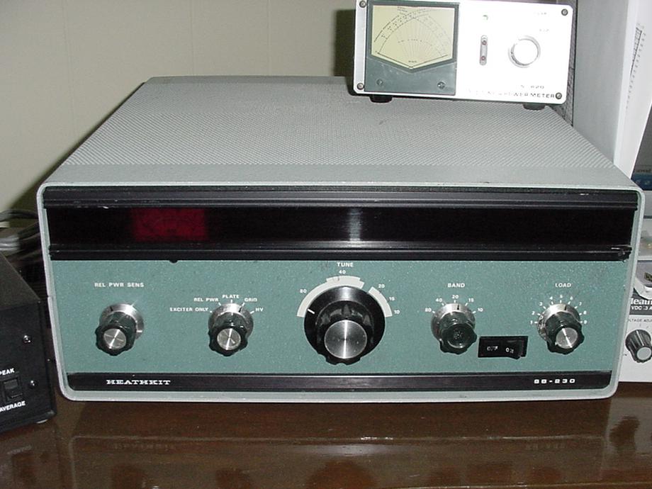
Left - Heathkit SB230 front view. |
 The HEATHKIT SB230 makes a perfect candidate for 50 MHz amplifier modification. There is lots of room to work with and it is a very stable
amplifier due to the 8873 tube. There are no problems with instability, which is common in glass tube modifications. You should expect to
get a good 600 watts output from this amplifier with a good tube. Shown below are pictures and notes on this modification.
The HEATHKIT SB230 makes a perfect candidate for 50 MHz amplifier modification. There is lots of room to work with and it is a very stable
amplifier due to the 8873 tube. There are no problems with instability, which is common in glass tube modifications. You should expect to
get a good 600 watts output from this amplifier with a good tube. Shown below are pictures and notes on this modification.If you have questions feel free to email me and I will try to help. Click |
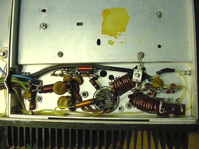
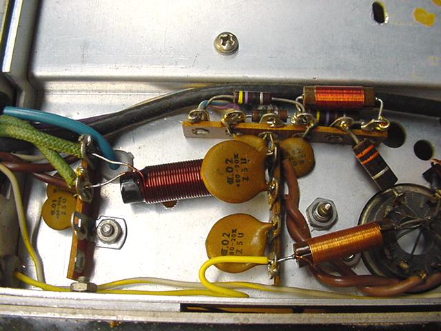
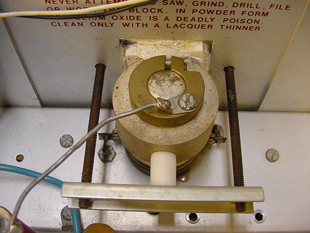
 Left - Here is a detailed picture of the input tuning components. It is important to completely eliminate the original input components and
add this circuit. This is the most efficient design and is easy to tune. The capacitor is a small ARCO type, approx 20-70pf. A small air variable
can be substituted.
Left - Here is a detailed picture of the input tuning components. It is important to completely eliminate the original input components and
add this circuit. This is the most efficient design and is easy to tune. The capacitor is a small ARCO type, approx 20-70pf. A small air variable
can be substituted. Right - A complete picture of the input circuit. All of the circuitry around the tube socket is original with the exception of the added input circuit. |

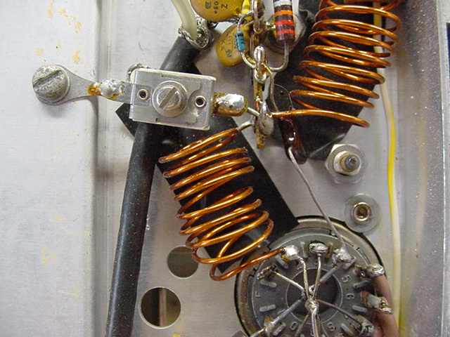
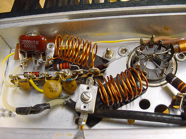
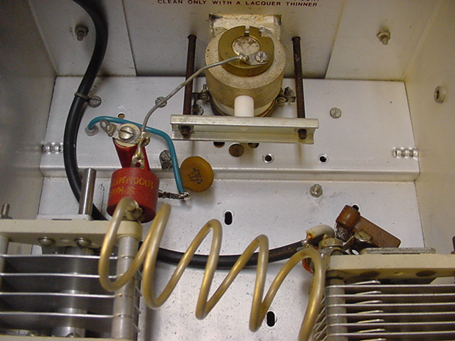
 Left - More detail of the complete tuning circuitry. Tune the input capacitor for maximum power and lowest SWR between the amplifier and your
exciter. Use caution as there is high voltage possible in this area.
Left - More detail of the complete tuning circuitry. Tune the input capacitor for maximum power and lowest SWR between the amplifier and your
exciter. Use caution as there is high voltage possible in this area. Right - More Detail of the output circuit. Both the load and tune capacitors are modified versions of the original capacitors. It is easy to remove plates and make a custom capacitor. This keeps the original holes all lined up instead of using junk box capacitors which may not have the same height. |
 Left - The best shot of this section including the 2000pf silver mica capacitors installed at the input connector.
Right - This picture shows the original tube socket wiring. This was not changed. |
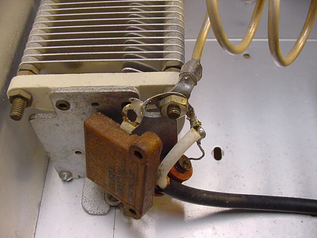
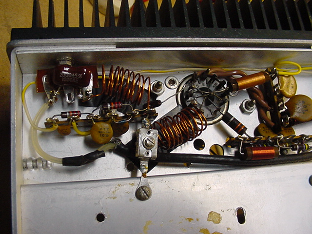
 Left - An overall picture of the completed output design of the amplifier. This is a very clean design.
Right - This shows the coil and load capacitor connections. Also shown is an addition fixed mica capacitor. This was added because I removed too many plates from the original capacitor. Leaving a few more plates in the original would allow you to eliminate this capacitor. A Z50 RF choke is also added at this point. |
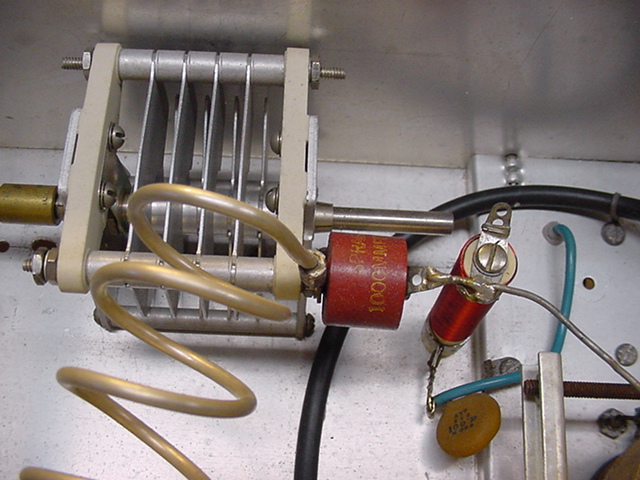
 Left - Showing the connections of the coil, tune capacitor, blocking capacitor and RF choke. The RF choke is original and no turns have
been removed. No parasitic choke is required in this amplifier.
Left - Showing the connections of the coil, tune capacitor, blocking capacitor and RF choke. The RF choke is original and no turns have
been removed. No parasitic choke is required in this amplifier.Right - This shows the modified tune capacitor as well as the coil, blocking capacitor and RF choke wiring. |
 Left - A close up of most of the output circuit.
 Right - A close up of the connection to the tube plate cap. |
|
|