|
K6JRF's Page formerly W6FZC AL-1500 EBS1 Ckt Analysis |
[Updated Spice RF Analysis of the AL-1500 EBS1 Ckt!]
If you have been here before, click here to see W8JI's latest "slight-of-hand"!
|
This page details some improvements that can be made to the Ameritron AL-1500 Electronic Bias (EBS1) Ckt. By use of 5Spice
RF analysis the ckt's operation is analyzed and detailed with recommendations for improvement. I switched from MSim's "PSpice" to a newer, more compact analysis program called "5Spice" written by Andresen Software. It features almost intuitive operation, has many powerful features and and allows the import of various Spice models so that the ckt can be simulated using the actual real world parts. Do a Google search to see more information on this fine circuit analysis product. The newest 5Spice release is V2.25 and it has some exciting features namely PWL auto repeat. See the analysis section below for more details and some actual simulation usage. The link below is an detailed analysis of one of the earliest (1975) ckt configuration. It didn't work as it was described and a detailed Spice analysis shows the required ckt component changes so that it does! Click here to download the PDF. |
|
Received this email . . . Hi OM, Your model is all messed up! The analysis is meaningless because you applied audio frequencies to the input instead of radio frequencies. The lowest possible frequency on the input is 1.8 MHz, not 10 Hz or even 3,000 Hz. Why would anyone model an RF detector with audio frequencies applied? 73, Tom W8JI An SSB signal consists of a "modulation" envelope, not a 'carrier' and this carrier-less signal is produced by both older and modern day transceivers. An AM signal has a "carrier" meaning that when the modulation stops, there's still a signal at the central RF frequency. With SSB, no-modulation means no-output and, of course, no carrier! This fact may seem trivial but W8JI uses a "carrier" to test the EBS1 ckt as if the signal were "AM" or a CW "tone". Back to "SSB"; modern day transceivers have wide band RF and AF ckts, allowing them to generate an "ESSB" [Extended SSB] RF signal output that contains modulation data typically from 50hz to 6Khz. Some specially modified transceivers can produce SSB envelopes with spectral info from 20hz to 9Khz! "Flex" radios can extend the modulation envelope to 20Khz! If a 50hz tone (from signal generator) is inputted into the rig's mic jack, the RF output is a SSB RF signal whose frequency is 50hz removed from the center frequency. It is this signal, when sent through an AL-1500 linear with a "stock" EBS ckt, that will emerge with severe envelope distortion. Since low frequencies (50hz) are easily outputted from the newer broadband radios (FT-2000, FT-9000, FT-5000, etc), the problem centers on the inability of most EBS ckts to pass this SSB envelope esp at low level b/c of three (3) main factors: low ckt gain, incorrect time constants and passband skew. Perhaps W8JI has not seen the comments from Richard, AG6K on RF actuated EBC ckts; "This is a desirable departure from the RF-actuated electronic cathode-bias switch circuits that have appeared in ham magazines. At first, "RF-actuated" sounds like it might be wonderful. However, these "RF-actuated" circuits result in the cathode bias-voltage being rapidly switched between nonlinear-cutoff and linear operation while the RF relays are in transmit. This often causes transmit audio to sound rough on softly spoken syllables and increases the IMD products that the amplifier generates." As he correctly stated, many bias ckts produce MORE distortion than is acceptable, so they are quickly abandoned by the user. The distortion consists of the tube's bias being switched from cutoff to normal causing the signal to sound muffled with what many observers call a "paper-crunch" sound. The power saving advantages of the ckt are offset by the distortion produced so many times this ckt is abandoned. If a Spice envelope analysis is undertaken, it can show where the ckt problems are and allow you to 'test' fixes to make the ckt operate as intended. The envelope analysis looks at the gain, passband of the EBS ckt at audio frequencies and that has W8JI upset. Certainly the SSB envelope is an "RF" envelope that contains the audio frequency info when demodulated in a SSB rcvr. Despite what W8JI incorrectly thinks, there's nothing wrong or incorrect about analyzing a ckt's response in this manner. Doing this ensures that the ckt works properly at both RF and Audio frequencies. Further, optimizing the ckt in this manner makes it "bullet-proof" when used in actual operation. To prove this, the section below uses a conventional Spice "RF" analysis to show the same EBS ckt problems as the envelope analysis does! Electronic BiaS Ckt [EBS]: 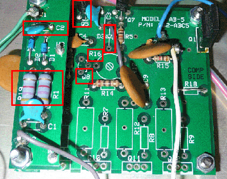 As you read in the AL-572 DBC analysis section, the AL-1500 linear also supports an a "electronic bias ckt" which is called the
EBS1 (Electronic BiaS) ckt. To me, all linears should have one! It saves the useless waste of "idling" power of
480 watts (3850V @ 125ma)!
 That said, recently, I found that this ckt restricts SSB Tx audio b/c of various ckt problems. This section is devoted to analyzing these problems and has suggested ckt improvements. Please read section on "R1 & R19 Replacement" at the bottom of this page. It's mounted near the opening of the fan plenum area and has a small "detector" board mounted on a standoff, just above it. As you see, I've marked the "missing" components which makes a difference in the simulation. This section features a Spice ckt analysis run at 2Mhz. This frequency is "inside" of the Ham Radio Band allocation as it sits between 160M (1.8Mhz) and 80M (3.5Mhz) ham bands. The "period" of 2Mhz is 0.5us, so it's easy to use that time to construct an RF signal to be used as the stimulus input to the EBS ckt. Most Spice programs allow the construction of "piecewise" linear signal, as does 5Spice. This gives the user a powerful tool to use with Spice's "transient" analysis to completely characterize the ckt under test. A sample of the "text" file used to produce a 30 watt RF signal appear below. It is simply the time representation of the RF amplitude. The excerpt shows two (2) cycles of the 2Mhz waveform. A "text" editor can construct the file needed. *SSB_2Mhz@30Watts * *enter waveform data points *comment: first data point is at time = 0 *data format: *time amplitude 0.000u 0.0 0.125u 54.8 0.250u 0.0 0.375u -54.8 0.500u 0.0 0.625u 54.8 0.750u 0.0 0.875u -54.8 1.000u 0.0 At time "0", the amplitude is "0" volts; at 0.125us, the amplitude is 54.8 volts-peak which represents 30 watts into 50 ohm load. The total duration of this test signal is 100us meaning that there are 200 cycles of "2Mhz" signal. Using this powerful tool allows one to determine the sensitivity (gain) of the ckt along with its "turn-on", "turn-off" and "hang" time. All this with just one stimulus signal. Since the EBS ckt is supposed to respond to " . . millewatts of signal" per W8JI, then 30 watts of RF drive should be overkill.
Stock EBS1 Ckt RF Analysis The schematic appears as shown here when captured into 5Spice's schematic editor. The values are the same as referenced in the "EBS1 Instruction Manual". Values are taken from the parts list in this manual. The EBS1 ckt board was tested in its as-delivered condition with R1 and R19 = 4.7K ohms. Please read the "R1 & R19 Replacement" note at the bottom of this page. 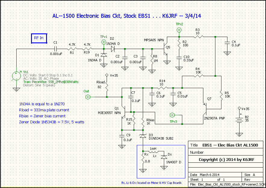
This revision has added the cathode ckt's zener diode for completeness. The zener is a 1N5343B, 7.5V @ 5watt. The actual zener is a 10W model but this chosen model does not effect analysis since the total current through the zener is kept to apx 400ma, which equals apx 4 watts of dissipation. From the Owner's Manual: "Q5 is a fast-attack, slow-decay switch, C10 sets the delay time with R2 limiting the charging current. Delay or "hang-time" is an additional period when bias remains at normal operating levels after the drive power goes to zero". In the zero-bias AL-1500 mode, C10 value of 0.33uF results in 150ms of bias hang-time. For adjustable bias operation, C10 should range from 2uF to 10uF. An approximation for C10 is C10 = bias voltage/3". 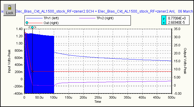 The chart shows the close-in detail of the RF signal applied to the stock EBS1 ckt. The "blue" line represents the RF signal
input; the "magenta" line represents the internal switch state; the "red" line represents the output of ckt.
The chart shows the close-in detail of the RF signal applied to the stock EBS1 ckt. The "blue" line represents the RF signal
input; the "magenta" line represents the internal switch state; the "red" line represents the output of ckt.The RF drive signal amplitude is 30Watts @ 2Mhz with a 100us duration (blue cluster). The turn-on time is 27us which is excellent and close to the Owners Manual claim of 20us. It s/b obvious that the turn-on time is dependent on the drive level but this fact is not mentioned. All appears to be "well" but it's not! |
|
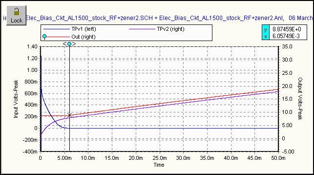 This chart shows that the "hang-time" is apx 6ms (8.8V bias) and NOT 150ms, not even close! Not sure how Tau = R*C would be 150ms for
R = 100 and C = 0.33uf. Tau actually is 30usec which mainly controls the turn-on time of Q5 along with C2 and C3.
The "150ms" hang-time can never be realized with those R/C values.
 Note that 8.8V bias is higher than the Eimac recommended value of 8.2V for class AB operation. Certainly if you allow for, say, 25V and still call that "legitimate" bias level (it's NOT!), the present ckt fullfills that requirement. However, the goal here is to operate the 8877 tube under EIMAC recommened class AB bias of 8.2V to produce a "clean" SSB Tx signal. More disturbing results in this next chart! |
|
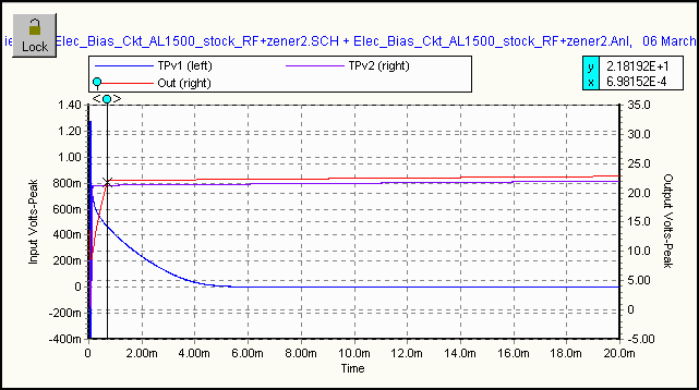 Changing C10 = 2.2uF (as suggested in the Owner's Manual) to increase the hang-time results in disaster!
 Carefully observe the "charging" action of the input signal (blue) in relation to the output (red) chart line. The bias almost immediately turns off at apx 700us to 22Volts. Hang-time has DECREASED!! How could that be??? The clue is the "purple" (TPv2) line shows the MPSA05 doesn't stay on after the drive signal is removed, so how can the output (red line) follow?? Answer, it can't! The simple fact is Q5 (MPSA05) does NOT have enough gain to supply the charging current to C10 so that's what happens. Q5 was a poor choice for the key transistor and the RC values need to be increased to get meaningful hang-time. Since transistor Q5 (MPSA05) has low current gain (BETA) and since it happens to be the "key" switching element in the EBS1 ckt means that this transistor determines whether the signal is determined to be "valid" by switching from "off" to "on". With low gain, the input drive signal MUST be raised to get Q5, MPSA05 to generate hang-time after the drive signal is removed. The bottom line, NO AMOUNT of INCREASED DRIVE will keep Q5 on after signal is removed. The chart for "C10 = 10uf" is even worse so it won't be shown. It just adds to the conclusion that a high-gain (Beta) transistor should be used for Q5. So the conclusions are that the stock EBS1 ckt will work with C10 = 0.33uF (maybe?) but not for any longer hang-time. Also the actual hang-time is apx 6ms, not 150ms. At this point, it's obvious that the stock EBS ckt does not have enough "gain" b/c Q5 transistor doesn't stay on after the drive signal stops. That low gain plus very short time constants equal a poorly functioning EBS1 ckt! Modified EBS1 Ckt RF Analysis The schematic appears as shown here when captured into 5Spice's schematic editor. The values are the same as referenced in the "EBS1 Instruction Manual" except for changes that resulted from the RF Spice analysis and on-the-air testing. The object here is to get a high sensitivity transistor for Q5 and increase the hang-time to 150ms. A 'good' electronic bias ckt, should switch on quickly so that the SSB Tx wavefront is fully allowed to pass. This implies that all frequencies within the wavefront should pass equally and it should delay in turning off so that any audio "effects" [ssb envelope modulation], if any, are fully "passed". The stock EBS ckt does not do this! 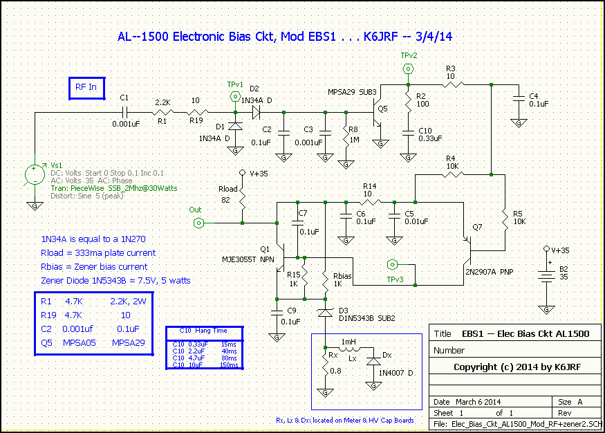 The chart shows the close-in detail of the RF signal applied to the modified EBS ckt. The "blue" line represents the RF signal input, 100us of 2Mhz @ 30 watt drive signal; the "magenta" line represents the internal switch state; the "red" line represents the output of ckt. The ckt changes are shown in the blue-colored table; R = 2.2K ohm; R19 = 10 ohms; C2 = 0.1uF and Q5 = MPSA29 transistor. The new transistor, MPSA29, is basically a "darlington" transistor meaning that there are two transistors inside the part feeding each other. The current gain (BETA) is extremely large (typ 5,000 to 10,000) and that translates into "high sensitivity" for low level signals. This is mandatory for proper operation of this ckt. This part is similar to the TIP122 used in the AL-572 DBC ckt and was substituted for the MPSA05 (hfe = 100) that is very short on required gain! 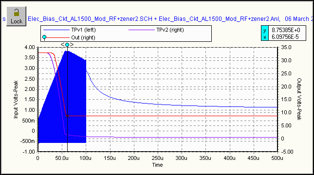 The RF signal integrating cap, C2 was increased to allow added hold time for the rectified drive signal at the base of Q5. Doing this
means that Q5's turn-on time will increase.
 C10 = 0.33uF: The ckt's output starts to turn-on at apx 26us, a bit slower than the stock EBS ckt's 10us. Note that at 61us, the modified EBS ckt has attained full class AB operating bias of 8.7V that remains stable for the chart's duration. The output remains stable (@ 8.7V) even though the RF input stimulus signal has now stopped. The output "holds" 8.7V level to the 500us time point and does NOT start to turn off! What you would expect from a properly operating EBS ckt. |
|
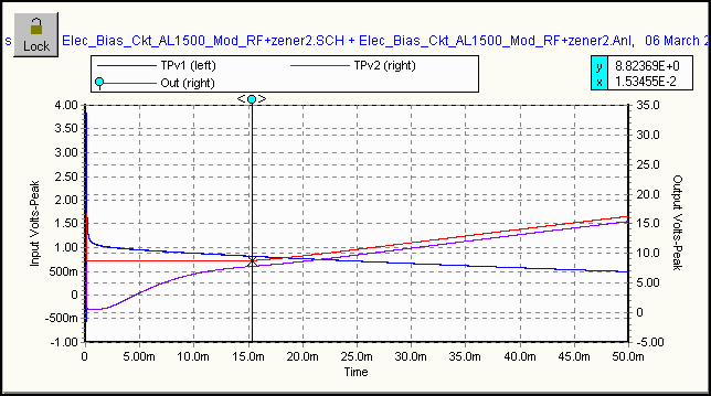 This chart shows the elapsed time up to 50ms. Note that the ckt's output is active sitting at 8.8V operating bias level at 15ms.
At this time point, it starts to rise and by 50ms, the bias point is 16V. The mod ckt has more than doubled the hang-time for C10 =
0.33uF.
 If you wish to lengthen the hang-time, select a cap value shown in the "C10 = Hang Time" table shown in the schematic above. For example, C10 = 0.33uF gives apx 15ms LINEAR hang-time. Note that this is the ckt's stock value, so no change is necessary. For increased hang-time, select the 2.2uF or 10uF caps for C10. |
|
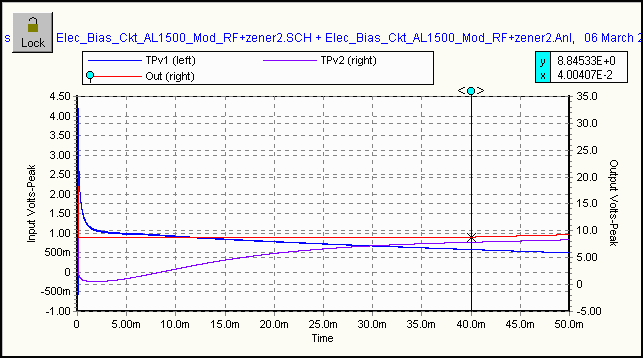 C10= 2.2uF: This chart shows the elapsed time to 50msecs. Note that the output (red line) holds steady at 8.8V @ 40ms mark.
This time represents the LINEAR hang-time of 40ms. Recall that for the "stock" EBS1 ckt, there was no output b/c of transistor Q5's
low gain. Not so with Q5 as MPSA29. Now the EBS1 ckt is a smoothly operating ckt!
 |
|
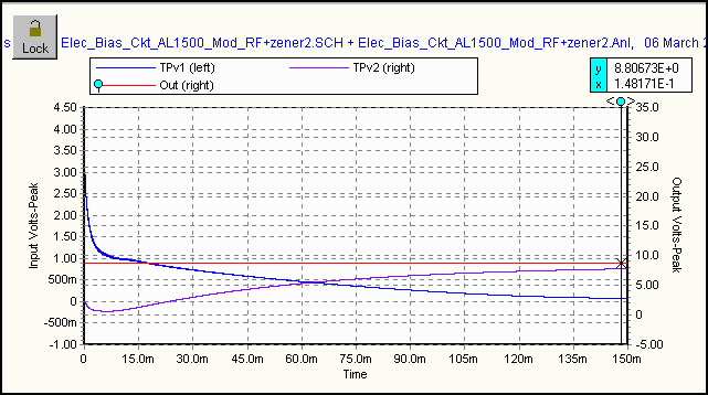 C10= 10uF: As suggested by the "Owners Manual", a larger C10 capacitor is used to generate increased hang-time. This chart shows
the elapsed time to 150msecs. Note that the output (red line) holds steady at 8.8V @ 150ms mark.
This hang-time is totally LINEAR (class AB) hang-time of 150ms. Recall that for the "stock" EBS1 ckt, there was no output b/c of
the ckt's inability to generate hang-time after the drive signal is removed! Not so with MPSA29 for Q5. A great operating EBS ckt
indeed!
C10= 10uF: As suggested by the "Owners Manual", a larger C10 capacitor is used to generate increased hang-time. This chart shows
the elapsed time to 150msecs. Note that the output (red line) holds steady at 8.8V @ 150ms mark.
This hang-time is totally LINEAR (class AB) hang-time of 150ms. Recall that for the "stock" EBS1 ckt, there was no output b/c of
the ckt's inability to generate hang-time after the drive signal is removed! Not so with MPSA29 for Q5. A great operating EBS ckt
indeed!I will stop here but I could show other RF stimulus inputs (2Mhz @ 5Watts for example) where the stock EBS ckt barely responds; the hang-time is even shorter than you've seen in the 10Watt analysis and for C10 = 2.2uF, the ckt doesn't operate. Is this a realistic input?? On 75mtrs, I drive the AL-1500 with 25 watts from the FT-2000D, so using 20watts and 40watts is meaningful. BTW, the modified EBS ckt operates identically with the 2Mhz @ 10watt and 20watt RF drive signals. The reason for the poor stock EBS ckt performance is readily apparent when you look closely at the Spice charts. Low ckt gain and non-optimum time constants chosen are the culprits. Low ckt gain should be neutralized somewhat if the input power is increased but even the use of 100W drive signal the stock EBS1 ckt still won't produce valid hang-time after the drive signal is removed. 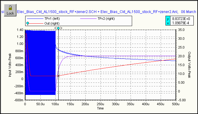 This chart (C10 = 2.2uF) clearly shows the detail from 0us to 100us for the stock EBS ckt driven by 100W 2Mhz signal.
Using this hi-power drive signal, let's look at a 500us time-slice for the stock EBS ckt's response. It turns-on about 20us as the red line shows and attains 8.8V bias (AB). And as long as the drive signal is "active", the stock EBS ckt is OK! After 100us, the drive signal ends and you see the ckt's hang-time, a mere 10us! At 110us, the ckt starts toward cutoff bias. A properly functioning EBS ckt is supposed to turn-on quickly (under 100us) and then provide hang-time (more than 50ms) when the signal is removed. If the ckt's time constants and ckt gain were analyzed by Spice, the ckt WOULD work with any form of signal transmission! The stock EBS1 ckt performs very poorly b/c it never switches fully on to provide operating bias (except in the hi power (100W) example above). If does turn-on, it drops out almost immediately when the drive signal is removed. For longer hang-times with larger values for C10, the ckt doesn't operate period! In all cases, its performance depends on the input power of the signal to a point; the higher the input drive power, the better it performs. Typical AL1500 drive power for full 1500W output is 30 - 45 watts. The modified EBS ckt works with as little as 10 watts input drive due to the use of a high-gain transistor used for Q5, MPSA29. |
|
|
W8JI incorrecty treats a SSB TX signal as a "carrier" and tests the ckt using CW "tone" or an "AM" signal. If the input signal
is as shown in the above example, the stock EBS ckt does operate marginally b/c of the carrier power level that gives enough
drive so the stock ckt operates using the "carrier" power to turn-on Q5. However, for longer hang-time delays, the ckt turns off
IMMEDIATELY after the drive signal stops, so it doesn't generate valid hang-time. For an SSB signal, there's no 'carrier' per se (other
than when it's present) so a low amplitude 50hz SSB RF envelope into the stock EBS1 ckt can not fully switch on, retain operating bias
for the length of the input and then provide hang-time when the signal is removed. All it produces is distortion! Low ckt gain
and improper RC time constants used in the stock EBS1 ckt are the cause of the problems. The ckt improvements make the EBS ckt a truly superb EBS ckt for any linear with any operating mode including QSK CW. Note that it fully meets the requirements for a "fast" turn-on (< 100us) and long hang-time (> 100ms) as stated in the design goals. And to boot, the cost of the modification parts is . . . . $2.50! So which EBS ckt do you want in your linear?
Final Schematic: The schematic below has all of the mods incorporated. 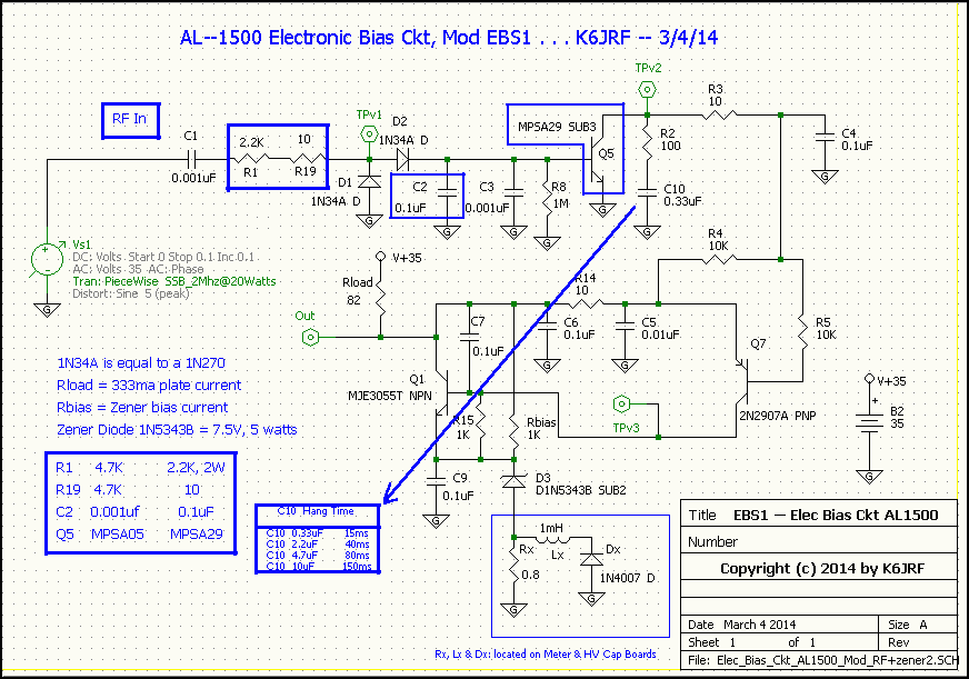
Parts Info: Some of these parts are very common and can be found in most electronic stores such as Radio Shack. However, much better prices can be obtained from Mouser Electronics and that's what I've used. Click the link for each part to see Mouser's price and availability. Ref Des ------ Value ------- Price/Ea ------- Link -------- Remarks C2 ---------- 0.1uF -------- $0.42 ------- -here- ------- 200V rating is ok: 50W drv = 141Vp-p! C10 --------- 2.2uF -------- $0.12 ------- -here- ------- 50V rating! C10 --------- 10uF --------- $0.19 ------- -here- ------- 50V rating! C10 --------- 4.7uF -------- $0.26 ------- -here- ------- 50V rating! Q5 -------- MPSA29 ------- $0.44 ------- -here- ------- drop-in replacement; beta=1K! R1 -------- 2.2K ohm ------- $0.95 ------- -here- ------- 2.2K ohm, 2W, 1% film resistor R19 -------- 10 ohm -------- $0.19 ------- -here- ------- 10 ohm, 1% film resistor C10 should be removed and replaced with the new value. Q5 must be unsoldered and replaced with the new part, MPSA29, which is a pin-for-pin replacement transistor. For R1 or R19 replacement, please see the "R1 & R19 Replacement" section. For up to 50W RF drive, I recommend using R1 = 2.2K ohm and R19 = 10 ohm. Q1 is an MJE3055 transistor which has 60V collector to emitter breakdown (Vceo) voltage. I MAY replace it with a TIP122 with a Vceo of 100V. This was the main replacement in the AL-572 amplifier's bias ckt as you read in that menu item. Time will tell if the present transistor can continue to perform without failure. So far after apx 3 years of linear operation, transistor (Q1, MJE3055) has not failed. Comments: The original analysis and mods were completed on 7/17/09 using Spice analysis. The EBS ckt has worked as Spice predicted! As new releases are made, more accurate analysis is possible so that's why I have re-visited the EBS1 ckt with the latest 5Spice release. The SSB envelope processed with the AL-1500's modified EBS ckt has no discernable distortion. The RF Spice analysis has shown the "same" problems as the previous analysis. What many fail to understand is that low frequency audio modulation (50hz for example) has much less amplitude than, say 1000hz signal. So with the EBS ckt's low gain, these low level signals are "distorted" b/c the stock EBS1 ckt can't fully attain and HOLD class AB operating (8.2V) bias as was clearly shown in the RF Spice analysis. W8JI incorrecty treats a SSB TX signal as a "carrier" and tests the ckt using CW "tone" or an "AM" signal. If the input signal is as shown in the above example, the stock EBS ckt does operate marginally b/c of the carrier power level that gives enough drive so the stock ckt operates using the "carrier" power to turn-on Q5. However, for longer hang-time delays, the ckt turns off IMMEDIATELY after the drive signal stops, so it doesn't generate valid hang-time. For an SSB signal, there's no 'carrier' per se (other than when it's present) so a low amplitude 50hz SSB RF envelope into the stock EBS1 ckt can not fully switch on, retain operating bias for the length of the input and then provide hang-time when the signal is removed. All it produces is distortion! Low ckt gain and improper RC time constants used in the stock EBS1 ckt are the cause of the problems. Reports from Hams on my AL1500 with the modified EBS1 ckt say my ESSB TX audio is "fantastic"! A "proof" was demonstrated by Tom, K6NHK with his AL-800H. He exchanged the recommended parts and the low frequency distortion was removed. His SSB Tx audio is perfect (I've heard it!). Emails from other Hams say they had the same results. I have no doubt that this mod would dramatically improve the SSB TX signal. The RF analysis have shown that problems exist with the stock EBS ckt and that the recommended changes do eliminate them! 5Spice V2 PWL Repeat Function 5Spice V2 (latest release V2.25) has an important tool for looking for changes in the transient analysis. They call it Piece Wise Linear (PWL) Repeat. By specifying a time at the end of the PWL file, the time is interpreted to be a repeat of the PWL function at the time specified. Sounds more complicated than it really is! The chart below shows the use of my 2Mhz @ 30Watt PWL drive signal repeating at 50ms and the resultant refresh of C10 time constant (C10 = 0.33uF). 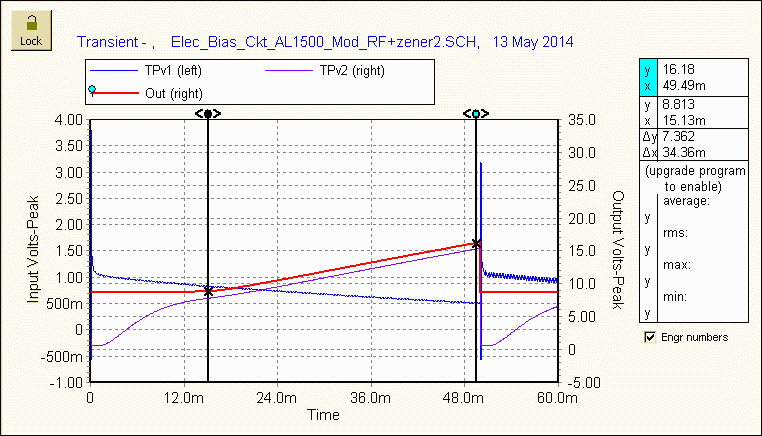
You can see that the Hang Time has reached 17 volts of cutoff-bias by 50ms where the PWL function is re-triggered. This action returns the ckt to the start condtions of 0us. Powerful simulation and analysis feature. |
| Send me |
