|
K6JRF's Page formerly W6FZC Garage Door Opener RFI Mod Photos by K6JRF |
(Posted: Dec 19, 2015 - Update: 10/30/20)
|
Garage Door Opener RFI Problems After 35 years my Genie Garage Door Opener (GDO) started to fail. BION, the motor and clutch were still functional but the control board was not long for this world. This unit used the fixed code 'strip' and worked quite well in that it never falsed once, even in my high RF environment! However, it is time for a new GDO.  I purchased a Guardian Model 628 unit and had it
installed. The noise difference in "dBs" was astounding. Genie employed a powerful screw drive but it sounded like a half-track
coming into the garage. In contrast, with the new GDO, you had to watch the garage door while it was opening/closing b/c it was
very difficult to hear it! Genie's screw drive track required yearly maintenance where the Guardian with its belt-drive, is much
less noisy and requires no maintenance.
I purchased a Guardian Model 628 unit and had it
installed. The noise difference in "dBs" was astounding. Genie employed a powerful screw drive but it sounded like a half-track
coming into the garage. In contrast, with the new GDO, you had to watch the garage door while it was opening/closing b/c it was
very difficult to hear it! Genie's screw drive track required yearly maintenance where the Guardian with its belt-drive, is much
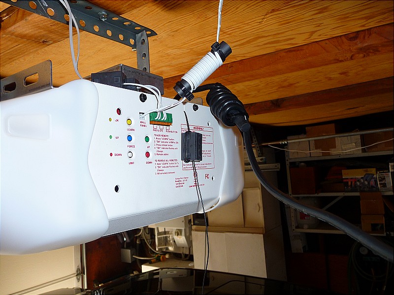
less noisy and requires no maintenance. Specs for the unit: 3/4 HP DC Motor 200W Lighting Electronic Limits <- great feature; eliminates travel limit switches Installer Force Adjustments <- allows for precise adjustment of closing force 5-Year Motor Warranty Interchangeable Integrated Rail Systems Now the 'bad-stuff'. I found the garage door wide open the next morning after the installation. I was on-the-air in the evening and the RF field must have falsed the GDO's logic board and caused it to open. I didn't know it was open all night. Not a good thing! Further testing confirmed that the GDO would consistently false (open or close) using low power RF SSB (150W) on 75 and 20 mtrs. That amazed me b/c it is digital and has rolling code technology. So how can an RF SSB envelope look like a 32 bit rolling code?? To false the GDO, I only needed to give my call sign and/or use the CW tuner (60wpm) to cause the door to open or close. That shouldn't be possible. There has to be another explanation. As I started the investigation into "what-is-the-main-culprit", I found that unplugging the wall-switch wire completely stopped the falsing! The GDO would still operate perfectly with the remote control. And try as I might, even with 1KW transmit energy, it would not false! This finding was expected b/c any unshielded long wire will act as an antenna. In my case, it required that the full length of the supplied connecting wire be used, some 50'. When a long wire such as this is exposed to an RF field, it WILL cause problems in any device not specifically treated to be immune to RF. So we now know the RF entry point. Next is how do I fix it? |
|
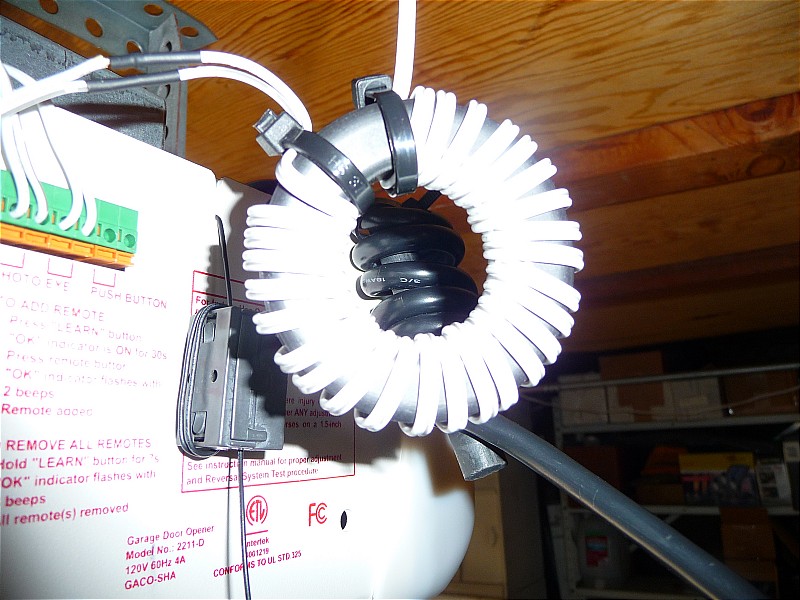
 So I constructed a HAM's favorite device; a ferrite core with the object wires wrapped tightly around the ferrite to form a
highly efficient RF choke. This simple device looks like high impedance to RF energy so it can't continue on the path.
[Subsequent measurements showed the choke at 13uH]. As you see, three 'chokes' were added;
one for the AC power, one for the wall-switch and one for the unit's antenna. Adding a choke on the AC power line is ALWAYS
a good thing b/c RF energy can enter a device through the AC power wiring in your home.
So I constructed a HAM's favorite device; a ferrite core with the object wires wrapped tightly around the ferrite to form a
highly efficient RF choke. This simple device looks like high impedance to RF energy so it can't continue on the path.
[Subsequent measurements showed the choke at 13uH]. As you see, three 'chokes' were added;
one for the AC power, one for the wall-switch and one for the unit's antenna. Adding a choke on the AC power line is ALWAYS
a good thing b/c RF energy can enter a device through the AC power wiring in your home. Why would you add one on the main antenna?? Won't that cause less signal to get into the unit's logic-board?? Actually it won't other than it has been shortened a little bit. The unit's logic board operates at 433.92 Mhz but the ferrite is a "short" at that frequency so it passes that RF with little or no loss. However, at 75mtrs, it looks like a choke. A case of having your cake and eating it too! |
|
 So after testing it on the highest frequency band (20 mtrs) and lowest band (75mtrs), it would false sometimes on 75mtrs but never on
20 mtrs. Ferrites exhibit increased attenuation as the frequency increases (to a point defined by the material, then it decreases), so
the conclusion is that the "impedance" is not high enough to stop the RF from entering the logic board at the lowest frequency.
Therefore, a higher impedance choke is needed.
So after testing it on the highest frequency band (20 mtrs) and lowest band (75mtrs), it would false sometimes on 75mtrs but never on
20 mtrs. Ferrites exhibit increased attenuation as the frequency increases (to a point defined by the material, then it decreases), so
the conclusion is that the "impedance" is not high enough to stop the RF from entering the logic board at the lowest frequency.
Therefore, a higher impedance choke is needed. I used the largest toroidal core (3.0" ID) and was able to double the original choke's 13 turns to 27 turns. [Subsequent measurment showed the choke to be 2.8mH]. The impedance now has been increased dramatically! The door could not be falsed. |
|
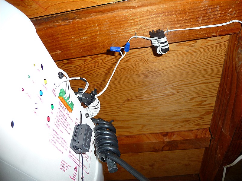 In order to be safe, I inserted a pre-filter consisting of 11 turns before the 27 turn filter [Measurement showed the choke at
76uH]. I used small wire nuts and inserted a disc-ceramic capacitor, 0.1uf*, to
form a distributed PI filter. Simply stated, this will guarantee that "zero" energy will be able to make it through the filter to the logic
board b/c the PI filter has a low-pass cutoff frequency of apx 43Khz!
In order to be safe, I inserted a pre-filter consisting of 11 turns before the 27 turn filter [Measurement showed the choke at
76uH]. I used small wire nuts and inserted a disc-ceramic capacitor, 0.1uf*, to
form a distributed PI filter. Simply stated, this will guarantee that "zero" energy will be able to make it through the filter to the logic
board b/c the PI filter has a low-pass cutoff frequency of apx 43Khz!
I completed construction on a small PC board that is a practical version of the filter that should fit inside of the GDO. This board contains smaller style inductors and two capacitors on a perf board of 1-3/4" x 1-1/2". Since the cover is easily removed, this filter board should fit nicely inside the unit and be out of view. See below for the new board details. * Capacitor not shown - added after the picture was taken. |
|
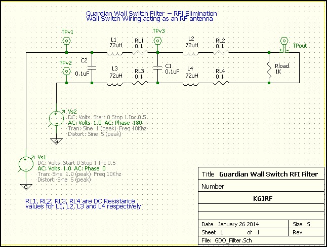 To see how well the new filter board would work, I bought some wire wound ferrite chokes [Measured value =
72uH] and used a Spice program (5Spice) to analyze the input vs output loss attenuation. I don't know the
logic board's input impedance for the wall-switch connection but 1 Kohm is reasonable assumption.
To see how well the new filter board would work, I bought some wire wound ferrite chokes [Measured value =
72uH] and used a Spice program (5Spice) to analyze the input vs output loss attenuation. I don't know the
logic board's input impedance for the wall-switch connection but 1 Kohm is reasonable assumption. This is the full detailed schematic showing the bifilar wound chokes; there are actually four (4) chokes, not just two. Since the filter board's "-" lead is 'ground' when inside the logic board, it's not from an RF standpoint when the two wire cable runs through the garage to the wall switch. The DC Resistance (DCR) value for each coil is included for completeness. During the final RF field testing, I found that the GDO falsed a few times randomly so the extra capacitor was added. After that I could not make it false. |
|
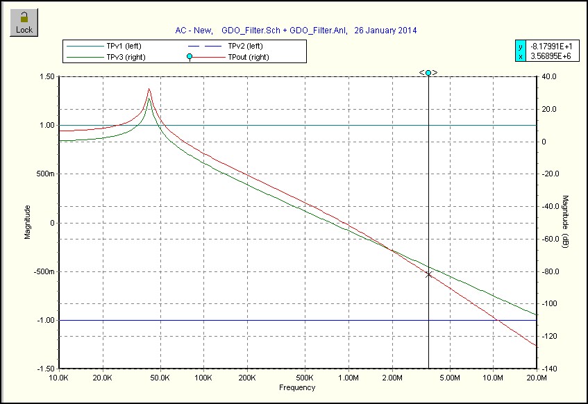 The graph shows the response of the total network plotted with frequency vs amplitude. At 3.55Mhz (represents 75mtr operation), the network
has attenuated the input signal by apx 81dB (red line). This means the signal has been
reduced by 11220 times. Starting at a 1V level, the signal is now 89 uVolts. That's why it can't false the GDO!
The graph shows the response of the total network plotted with frequency vs amplitude. At 3.55Mhz (represents 75mtr operation), the network
has attenuated the input signal by apx 81dB (red line). This means the signal has been
reduced by 11220 times. Starting at a 1V level, the signal is now 89 uVolts. That's why it can't false the GDO!
|
|
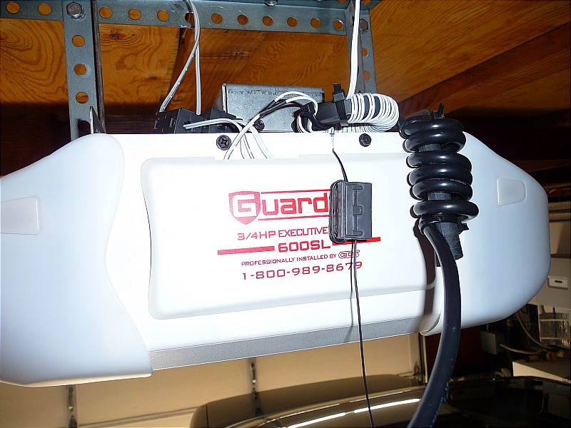 Here's the interim solution with the GDO's front plate installed. The large toroidal core sits on top. You'll notice that
there are two small 'snap-open' cores added to the photoelectric door lines to ensure RF free signals.
Here's the interim solution with the GDO's front plate installed. The large toroidal core sits on top. You'll notice that
there are two small 'snap-open' cores added to the photoelectric door lines to ensure RF free signals. I was on-the-air for over 2 hours most nights this week, running high power, 1.5 KWatts and there was no falsing problems whatsoever. The problem is history and I'm glad it is. The story here has a happy ending with the addition of some simple RFI techniques. Now replace this solution with the perf board filter detailed previously. |
|
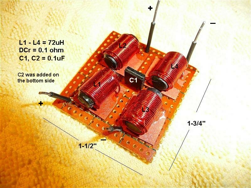 To be able to install a "practical" filter version inside of the GDO, the size and bulk must be reduced. The picture shows the rebuilt
filter mounted on a small perforated board ready to mount inside of the Guardian Model 628.
To be able to install a "practical" filter version inside of the GDO, the size and bulk must be reduced. The picture shows the rebuilt
filter mounted on a small perforated board ready to mount inside of the Guardian Model 628. Each inductor is apx 60uH - 70uH with DC Resistance (DCR) of less than 0.1 ohm. Low DCR is required so that the DC control voltage provided from the GDO to Wall Switch is not effected. The capacitors are a hi-Q ceramic 0.1uF. The parts (L1 - L4 + C1, C2) came from my "junk" box so the wasn't any appreciable cost.
|
|
 After removing the outside cover and looking closely at the Logic Board, it would be impractical to mount the new filter board inside of
the unit b/c the wall-connector is mounted directly to the Logic Board. This means that the Logic Board would need modification which
is not feasible. So plan "B" was used.
After removing the outside cover and looking closely at the Logic Board, it would be impractical to mount the new filter board inside of
the unit b/c the wall-connector is mounted directly to the Logic Board. This means that the Logic Board would need modification which
is not feasible. So plan "B" was used.Here the Filter Board was mounted on top and held down with Velco strip. This is the simplest way to do it and makes it "almost" invisible. The GDO + new filter were tested on 75 and 20mtrs @ 1.5 KWatt level with a random door-false every once in awhile. So an additional capacitor was added (C2) for extra attenuation. After that, the door could not be falsed. |
|
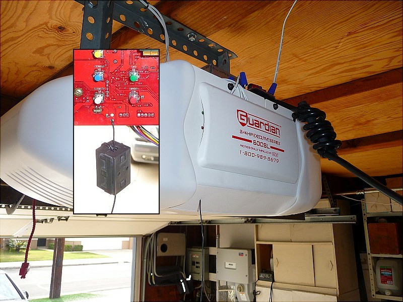 The "final" picture shows the Guardian Model 628 GDO with the cover added. The filter board is almost invisible and it does make this GDO
RFI-proof! The AC line filter was also kept b/c it's a good safety factor.
The "final" picture shows the Guardian Model 628 GDO with the cover added. The filter board is almost invisible and it does make this GDO
RFI-proof! The AC line filter was also kept b/c it's a good safety factor.The 433Mhz receive antenna was relocated to come out the bottom cover as shown in the picture. Originally the antenna is looped back, passing over the Logic Board so it can come out at the top. This is not optimal for two reasons; it makes the Logic Board more suspectable to RF pickup and the antenna is not as effective as if it was hanging straight down. My tests showed that the GDO would operate with the remote at distances to 110 ft reliably with the 2-turn ferrite choke. The inset picture shows the internal ferrite choke that performs two tasks; it make the antenna less susceptible to RFI pickup and provides strain relief so if it's accidently "pulled", it can't break b/c the choke rests on the inside-bottom of the cover. |
|
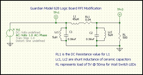 The key is to success is to find small parts b/c of the limited space to do the modification. Also the choke must have very
low DCR b/c it must pass the control current for the wall switch LEDs. Chokes, called "bead-chokes", used in solid state amplifiers are
perfect for this task b/c they have high inductance with very low DCR (0.04 ohms). Two of these wired in series produce a 45uH choke with
virtually no DC loss. The two ceramic caps (0.39uF) are 50V units and are extremely small.
The key is to success is to find small parts b/c of the limited space to do the modification. Also the choke must have very
low DCR b/c it must pass the control current for the wall switch LEDs. Chokes, called "bead-chokes", used in solid state amplifiers are
perfect for this task b/c they have high inductance with very low DCR (0.04 ohms). Two of these wired in series produce a 45uH choke with
virtually no DC loss. The two ceramic caps (0.39uF) are 50V units and are extremely small. The schmatic of the pcb version shows a simulation using the parts chosen. The choke's series DC resistance 0.04 ohms along with the ceramic cap's shunt inductance has been included to insure accurate modeling. |
|
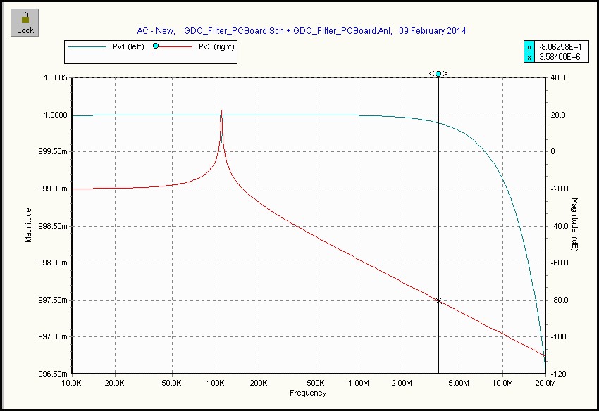 Compare the attenuation of this smaller filter with the original filter above. The output attenuation, -80dB, is almost identical to the
large original filter but it takes up much less space forming a very compact package. It shows that small filters can be built that produce
outstanding results. Also the price of these parts is less than $1.50!
Compare the attenuation of this smaller filter with the original filter above. The output attenuation, -80dB, is almost identical to the
large original filter but it takes up much less space forming a very compact package. It shows that small filters can be built that produce
outstanding results. Also the price of these parts is less than $1.50!
|
|
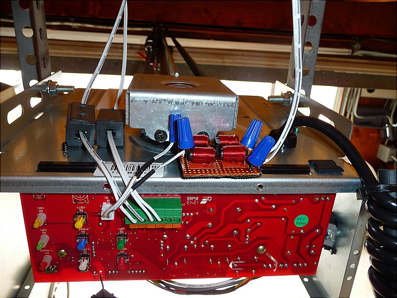
 As a long time electronics design engineer, the picture shows where the RFI filtering should be done. The J8
connector terminates the Wall Switch cable and also supplies 5V to the LEDs in the wall switch. The "-" side
is the Logic Board's ground plane so only the "+" side would need RFI parts.
As a long time electronics design engineer, the picture shows where the RFI filtering should be done. The J8
connector terminates the Wall Switch cable and also supplies 5V to the LEDs in the wall switch. The "-" side
is the Logic Board's ground plane so only the "+" side would need RFI parts.The parts (45uH choke w/ low DCR and two disc ceramic caps, 0.39uF) incorporated where shown would eliminate the RFI problem giving apx -80dB attenuation to any RF signal. The picture shows the scale of the added parts; apx 1:1 size in relation to the pc board. The inset shows the electrical schematic for the added parts. This means that the Logic Board's artwork should be modified to incorporate the RFI filter. This would ONLY be feasible if it needed updating for other reasons. The filter parts could be included at that time at minuscule cost. |
|
|
Summary and Conclusions It should be noted that the Guardian Model 628 is not substandard, deficient or defective in any way. It operates perfectly in an NON-RF environment. I can state this unequivocally after my extensive testing. Further, all GDOs that use rolling code technology contain one logic board to minimize costs. GDO's such as Liftmaster, Genie, Stanley, etc. are some examples that will perform identically when placed into a strong RF environment such as mine. The question centers about how many GDOs will be operated in a strong RF environment?? Very, very few. So that's why the extra cost of adding RFI perventative measures is not done. Only if the GDO finds itself in an high RF field will the lack of RFI design cause a problem. My tests proved this. Fortunately, this nasty problem is easy to remove using readily available, inexpensive parts. Whether is done 'overboard' as my first solution or incorporated into the artwork of the Logic Board, it will permanently solve the problem for ANY user. Also the final solution (shown above) is actually much cheaper to implement than the interim fix. Now my GDO operates perfectly even in my severe RF environment. It's a pleasure to use! 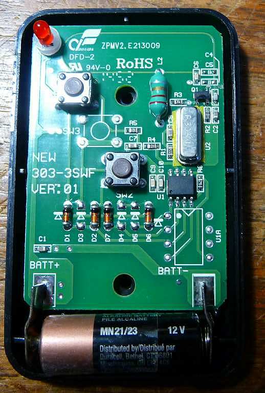 Update: [10/30/20] Add a Keypad to the Guardian GDO
 Prior to my RFI testing, an interim fix was tried that replaced the 'standard' 303 Mhz logic board with a more secure logic board operating at 433.92 Mhz. That's what I was told however today I found that it was just a NEWER version of their standard 303Mhz board. I found absolutely no difference in terms of RFI reduction between either board. George Robinson is a Customer Support Specialist [Tel: 562.948.1816 - Email: georger@adhguardian.com ] and is very knowledgeable about all Guardian products. He stated that there is a keypad for a Guardian 628 with a 433M board. However, after looking at the remote's back panel, it clearly shows that it's a 303Mhz model. To be sure, I took it apart; the picture shows the detail. If you look closely the crystal is marked "303M" denoting the oscillation frequency. Tnx George for getting this problem clarified! I've successfully added an external keypad, model WKCC-1 keypad. Here's the info required to setup the Guardian WKCC keypad. Consulting the 628 installation manual is no help: it states that you should follow the instructions given with the keypad. The installation and programming manual for the Guardian WKCC is here 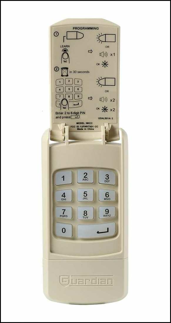
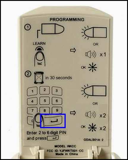 Summarizing the installation "video" and the above Installation Manual gives the following steps:
1) Press the "LEARN" button on the Guardian 628 operator - you will have 30 secs to program the WKCC; 2) Enter a four-to-six digit code, then press "Enter". The button is shown highlighted in "BLUE" 3) The light on the Guardian 628 will flash and 'beep' twice. 4) Programming is complete. Next time the correct code is entered, the door will go up (if down) or down (if up). Note that even if the garage door is "locked" (sliding the control lever on the wall control unit to "lock"), the garage door will OPEN if the correct code is entered on the keypad! So keep the code private! |
|
|
Update: Earl, WB9UWA wrote that his
Genie Chainmax 1000 produces RFI through the
door sensor outputs which is detected on 80mtr in his receiver. So he built the PCB filter which didn't work b/c there wasn't enough
attenuation for the large amount of RFI coming from the GDO. He then built a 31 turn toroid using
FairRite 43 material that suppressed the RFI. Personally, I believe the GDO is defective but still can be 'tamed'!
Update: Frank, K8FB wrote me explaining his RFI problem on the newly installed Guardian Pro Series 615 model. With 100W CW on 30mtrs, the garage door was found open the next morning. He disconnected the manual wall button and the RFI went away, He added an L-C filter to cure the problem. He told me that Guardian has added a link to their SERVICE page for "RFI" problems! Check it out here. Click the link "Garage Door Opener RFI Mod". Don't be surprised . . . it takes you to this page! Good thinking by Guardian! |