|
K6JRF's Page formerly W6FZC ESSB Audio Techniques Page |
(Update: Jun 14, 2015)
|
This Technical Note details how disassemble the FT-2000 Front Panel to repair the "Vox" button.
|
|
Of all things that could fail in today's complex radios, the VOX button would be my last guess. But, about 2 years ago (2011), it did fail and I decided to fix it. It's a lot of work just to get to it but it beats boxing it up and sending it away to Yaesu for repair. And, it's a lot cheaper!
Problem: As you know, on most radios, you press the button and it activates the function and, in Yaesu radios, it also illuminates as positive feedback that the function is now active. Simple enough. It started to fail about 3 months earlier when the VOX button was pressed, sometimes it wouldn't activate. As the problem got worse, I had to press the button using 'diagonal' pressure to activate it. Finally, pressing it did nothing! I suppose many would not give this a second thought, since many HAMS never use Vox. I do use it almost exclusively since I've tailored it to respond to the male voice here. Click to see what that entails. Method: 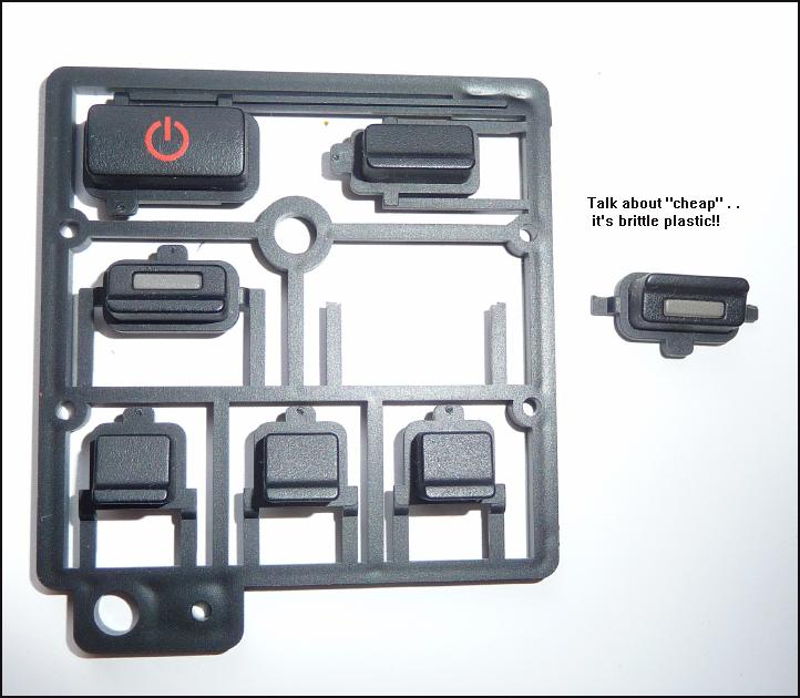 Using the FT-2000 Service Manual here, the exploded diagrams show what needs
to be removed in order to gain access to the "Knob Assy", PN RA084380A.
Using the FT-2000 Service Manual here, the exploded diagrams show what needs
to be removed in order to gain access to the "Knob Assy", PN RA084380A. The PN has now changed; RA084380B according to Sheldon, WA6KJN. This can be purchased from Yaesu Parts for apx $6.50. As you see, the "knob assy" is delivered as a "punch-out" that contains the Power Switch, Dim, Mox, Vox, Tune, 1/2 and Rx reading from top left to bottom right. You simply select the needed button and cut it out. Pretty straightforward operation. The picture shows the "VOX" button removed from the assy. The good part is you have extra buttons if needed for future repairs. WA6KJN suggests that you replace the complete assy and use AS-IS. Looking at the SM exploded assy, the complete PB Assy is shown and that implies that the COMPLETE ASSY should be replaced. You will have to remove the seven (7) screws holding the SW-A Unit to replace the complete PB Assy. Thinking back, I believe that is why I only replaced the VOX PB b/c I only had to "loosen" some of the seven (7) screws to get the new VOX PB into place. In over four (4) years, the new VOX PB is working well and there hasn't been any additional failures. The main diagram for finding what needs to be removed is shown in the SM on sheet "Exploded View-3". If you are brave enough to tackle this job, then following the exploded views shows all of the required screws, etc that need to be removed. It goes w/o saying that you need to remove the top and bottom panels first. Now you are ready to tackle the front panel removal. |
|
|
The required steps for disassembly: 1) Remove the front panel knobs as shown below. 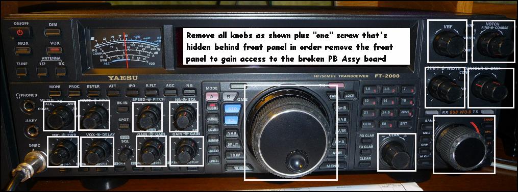 2) Make a "hinge". 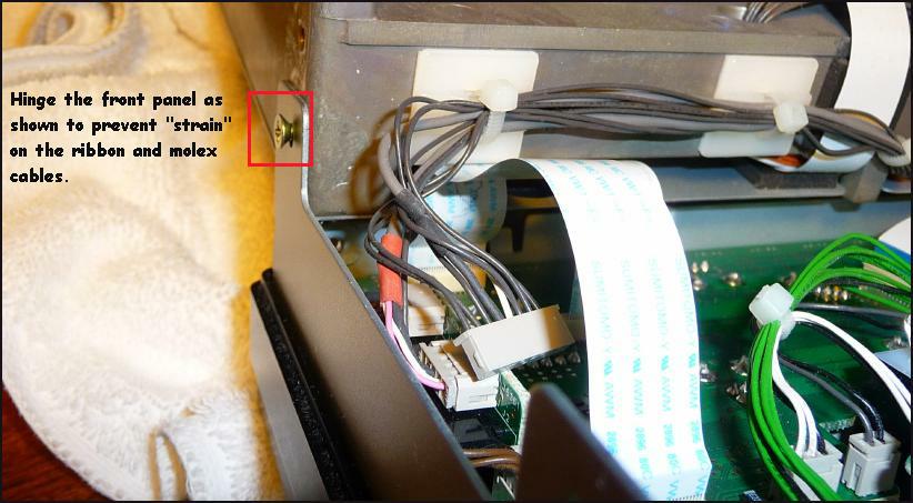 As you see, there's a large number of cables that need disconnecting. Take you time and carefully disconnect them by pulling equally across each ribbon cable's connector or rock the Molex connector gently back and forth to remove it. For insertion, open the Molex connector fully while sliding the ribbon metalized end into the connector so that it's fully seated. May take a little practice but take your time. It's important to fully seat the cable. 3) Once all cables/connectors are removed the front panel is now free as shown below. 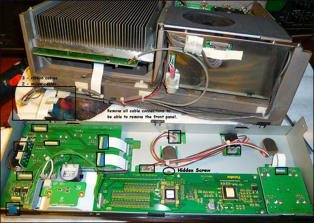 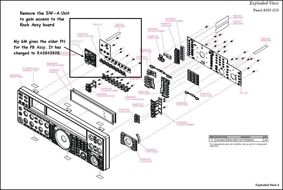 |
|
Send me |