|
K6JRF's Page formerly W6FZC FT1000D 2nd Receiver Page |
|
This 2nd Rcvr Page details the required modifications needed to the FT1000D 2nd
receiver to pass higher frequency audio as detected during transmit using the 'MONITOR' function.
Note 5 details all of this. |
|
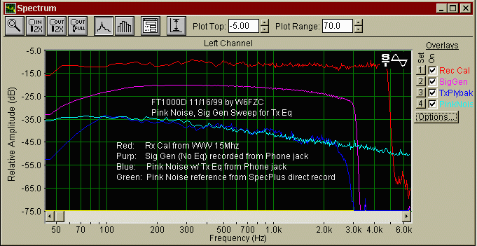
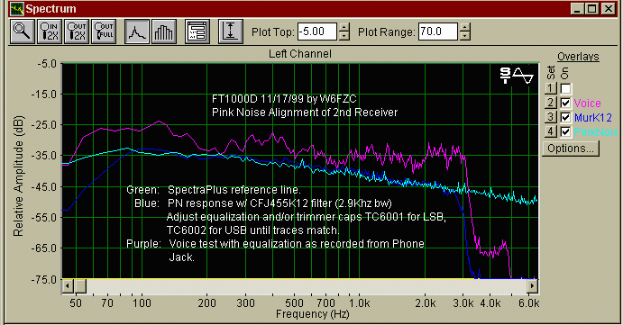
NOTE 5 This report details changes to the FT1000D 2nd Receiver Unit resulting in wider bandwidth via the phone jack by replacing the CF6002 filter. Also a novel method of alignment using pink noise is explained.The FT1000D uses the 2nd receiver unit during transmit as the signal monitor when the 'MONI' switch is pushed. The output is made available from the front panel phone jack. The receiver uses a Murata CFJ455K15, 2.4Khz bw ceramic filter which matches the 2.4Khz transmit bandwidth of a stock radio. With the addition of the wider InRad filters described in the other notes, taking the radio to 3Khz bw, the monitor receiver now lacks some fidelity. The following adjustment procedure requires SpectraPlus (SP) from Sound Technology (or equivalent) to accomplish the Tx alignment. I use mine in conjunction with my laptop to form a mobile alignment and calibration tool. The use of pink noise results in a time saving, accurate method of aligning any signal path assuring a flat frequency response. Analysis (Stock): The attached chart jrf_TxEq.gif shows the shows the response of a stock FT1000D radio using a Murata CFJ455K15 (2.5Khz bw) filter. The AQUA line represents the reference line. This was accomplished by recording the SpectraPlus pink noise signal onto a Sony Minidisk recorder (MZ-R55). Next it was recorded into the laptop using SP to form the reference line. Later on in the procedure, it will be used as a signal generator to the radio while the SP on the laptop accomplishes the recording. This line displayed represents a classic response that drops 3dB per octave. This represents FLAT frequency response! The BLUE line represents the result of the playback through the FT1000D with equalization via my dBx Pro DDP unit. Note that the bandwidth is 90hz to 2.4Khz. This is determined by the existing Murata filter. See notes in INSTRUCTIONS for how-to-install. The PURPLE line is sweep from the HP3310A signal generator directly in the mic jack with NO equalization. This line represents what a raw signal would like look if re-transmitted. Analysis (Modified): The attached chart jrf_TEq1.gif shows the shows the response of the modified FT1000D radio with a Murata CFJ455K12 (2.9Khz bw) filter. The AQUA line represents the reference level as before. The BLUE line represents the result of the playback through the FT1000D with equalization via the DDP unit (channel 2). Note that the bandwidth has been increased: 70hz and 3Khz. See notes in INSTRUCTIONS for how-to-install. This is determined by the new wider Murata filter. To adjust for flat frequency response, play the PN signal and adjust the appropriate trimmer cap on the 2nd receiver, TC6001 for LSB and TC6002 for USB. You will need to adjust the amount of equalization and each trimmer capacitor in turn until the curves match as close as possible (blue vs. aqua). The PURPLE line represents a standard voice test as recorded from the equalized output phone jack. This signal is now capable of making accurate recordings to 2.9Khz bw on tape, wave, minidisk or other media.
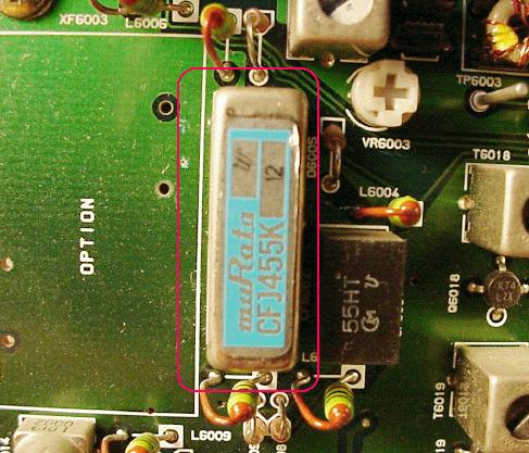
The following instructions for gaining access to the 2nd Receiver Unit and its removal. 1) Remove top and bottom covers of the radio. With the radio on its side left side, located the 2nd receiver unit. Remove the shield cover from the unit. Next remove the seven (7) screws that hold the unit down. Remove the J6004 connector. Next cut the cable tie that hold the unit's cable assembly down. Next, gently lift up on the board and flip it over. 2) Locate CF6002 filter in the bottom left of the board. It's the only Murata filter on that board. Using the appropriate soldering iron, remove the solder from the four (4) terminals and one (1) ground. Note: If you have never de-soldered from a large ground plane board, this part may best be left to someone who has! The use of a large tip iron with controlled heat is necessary in order to remove the solder. The ground plane acts as a very efficient heat sink! Remove the old filter and store it away. 3) Insert the Murata CFJ455K12 filter and solder the four (4) pins and one (1) ground. This filter was removed (many years ago!) from a TS-940AT. The part should be available from Kenwood. The Kenwood part number is L72-0333-05 and they are available at $70.81 each. Of course, any alternate filter is acceptable provided that it has a 'CFJ' form factor. 4) Replace the board but first slip a mini cable tie through the chassis tie point. Dress the cable assembly and replace the seven (7) screws. Put the shield cover back into place. COMMENTS: The change results in very pleasing and accurate audio via your headphones when used with wideband headphones. The Yaesu YH-77st are exceptional! |
|
2nd Rcvr Mod Results The results of the changed Murata filter is shown here. Note that a un-soldering is required to do this enhancement.
|
|
Send me |