|
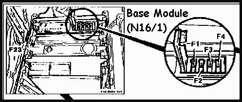
Base Module N16/1
Description and Operation
 The Base Module (BM), N16/1 controls the power distribution to the individual control modules and various output devices.
The BM also houses the fuses for many of these components. The color code is BLACK.
The Base Module (BM), N16/1 controls the power distribution to the individual control modules and various output devices.
The BM also houses the fuses for many of these components. The color code is BLACK.
Components powered by the Base Module
F1 Fused voltage supply for:
- Stop lamp (S9/1)
- ABS (N30) or ABS/ASR (N30/1) control module
- ASD (N30/2) control module
F2 Fused voltage supply for engines 104, 119 up to 9/92:
- "CHECK ENGINE" malfunction indicator lamp (MIL), A1e26
- LH-SFI control module (N3/1)
- Diagnostic module (N59) on California engines
- Fuel pump relay module (K27)
- Ignition control module (N1/3) knock sensor
- Secondary air injection relay module (K17)
- Transmission upshift delay relay module (K29)
- Upshift delay solenoid valve (Y3/2)
- EGR switchover valve (Y27)
- Adjustable camshaft timing solenoid (Y49)
- Left adjustable camshaft timing solenoid (Y49/1)
- Right adjustable camshaft timing solenoid (Y49/2)
- Purge switchover valve (Y38/1)
- Fuel injectors (Y62)
 F2 Fused voltage supply for engines 104, 119 as of 9/92:
- "CHECK ENGINE" malfunction indicator lamp (MIL), A1e26
- LH-SFI control module (N3/1)
- Diagnostic module (N59) on California engines
- Fuel pump relay module (K27)
- Ignition control module (N1/3) knock sensor
- Fuel injectors (Y62)
F3 Fused voltage supply for:
- SPS (N49/1) control module
- ADS (N51) control module
- TCM (5-speed automatic (N15/1) control module
F4 Fused voltage supply for:
- Secondary air injection relay module (K17)
- Fuel pump relay module (K27)
- Transmission upshift delay relay module (K29)
- EGR switchover valve (Y27)
- Adjustable camshaft timing solenoid (Y49)
- Left adjustable camshaft timing solenoid (Y49/1)
- Right adjustable camshaft timing solenoid (Y49/2)
- Purge switchover valve (Y38/1)
Fault Table, DTC Readout, Base Module (N16/1)
Socket 1: Black (Ground)
Socket 3: Red (+12.5V)
Socket 8: Yellow (Pin for BM DTC readout)
| DTC Readout |
Possible Cause |
| 1 |
No Faults in System |
| 5 |
Maximum allowable temperature in module box (F23) exceeded |
| 6 |
A/C electromagnetic clutch (A9k1) jammed or poly-V belt broken |
| 7 |
Poly-V belt slips |
| 8 |
Engine 120: Left LH-SFI control module (N3/2) voltage supply, open circuit |
| 9 |
Engine 104, 119: LH-SFI control module (N3/1) voltage supply, open circuit
Engine 120: Right LH-SFI control module (N3/3) voltage supply, open circuit |
| 10 |
Base module (N16/1) voltage supply output fuse F2 open circuit |
| 11 |
Base module (N16/1) voltage supply output fuse F3 open circuit |
| 12 |
Base module (N16/1) voltage supply output fuse F1 open circuit |
| 13 |
Base module (N16/1) voltage supply output fuse F4 open circuit |
| 15 |
Kickdown switch (transmission mode) (S16/7), short circuit |
| 16 |
A/C electromagnetic clutch (A9k1), short circuit |
| 17 |
Module box blower motor (M2/2), short circuit |
|