|
On/Off Ratio Testing (Lambda)
Testing Lambda control system with On-off ratio tester
The correct operation of the Lambda control system is the most important control function in the vehicle. The object of this
control system is to keep the air-fuel mixture to within 2% of 14.7:1 ratio for all operating conditions. In this way, the
catalytic converter can then process the three major pollutants, HC, CO and NOx. The catalytic converter burns the HC and
CO to produce water vapor and carbon dioxide. The NOx emissions are 'reduced' and produce nitrogen and oxygen.
The operation of the Lambda system can be checked with the On-off ratio test. It can also be used to identify momentary faults
not stored in fault memory. Faults are distinguished between those that occur with the ignition on and those that occur with
the engine at idle.
Technic Tool Supply is now doing business as "GermanCarToolPlus". The direct link to their site is
here. Their Lambda Tester's direct link is no longer active but appears to be
the same as their previous "M0039" tester which I have tested on my S500. It also can used to adjust the CO levels in vehicles
that have adjustment capability (S500 does NOT!) Please contact them directly with any questions you may have.
The On-off ratio can be checked with any suitable multimeter that has a "duty cycle" function. There are many availalble at
various prices, so I won't recommend one here.
Set the meter for duty-cycle, put the postive lead into #3 pin of the X11 connector on the left side fender well. Put the
negative lead into #2. Start the engine and let it warm up. Unless there are other problems the duty cycle should not vary
much more than 7% either way of set center, 50% after the car is fully warmed.
For the X11 connector, the O2 sensor is on pin 3; pin 2 is ground and pin 6 is battery voltage (12.5Vdc).
This connector is applicable to all Mercedes-Benz models starting from 1980. Note that in 4/94, MB discontinued use
of the X11 connector. The signals were moved to X11/4 and are on pins:
Pin 13, TN; Pin 14, OS1; Pin 15, OS2.
O2 Sensor Testing
If you suspect that you have a worn/bad O2 sensor, it can be tested both ON and OFF the car. The following test describes
how to test it OFF the car. Doing it in this way is usually quicker since the test parameters can be manipulated easier.
Use a high impedance DC voltmeter (VOM) with at least 1M ohm/volt. This will not load the O2's output signal. Clamp the sensor
in a vice. Attach the negative lead of the VOM to the case or the ground lead on the connector. Attach the positive lead to
the output wire. If there's a "heater" wire (probably is), it does not need to be connected for this bench testing. Use a
propane torch with a high flame and place the tip of the inner blue flame on the slotted or perforated area of the sensor.
You should see a DC voltage of 0.6V MIN within 20 seconds. If not, the most likely cause is open circuit internally
or the sensor has been lead fouled.
If OK so far, remove from flame. You should see a drop to under 0.1 volt within 5 seconds. If not it is very likely
to be silicone fouled. If still OK, heat for two minutes and watch for drops in voltage; it should be steady with no drops.
Sometimes, the internal connections will open up under heat. This is the same a loose wire and should be considered as a
bad O2 sensor.
If the sensor is OK at this point and will switch from high to low quickly as you move the flame, the sensor is good.
Any O2 sensor that can generate 0.8 volts or more when heated, show 0.1 volts or less within one second of
flame removal, and pass the two minute heat test is good regardless of age.
However, I suspect that many are barely operable with 100K+ miles of on-engine use. I personally recommend replacing it
after 60K miles. So does Bosch!
Lambda testing for 1995 and later MB vehicles
In early '94, the MB factory discontinued use of the X11 9 pin connector. For these vehicles, a special adapter cable/box is
needed. PN is 900 589 0115 00. This adapter plugs into the 'A' an 'B' connectors on the Ignition Control Unit (N1/3) and
allows the necessary signals to be accessed as they were in the discontinued X11 connector. The 'box' end of this adapter
has a mating 9 pin plug compatible with the standard On-Off ratio's connector. Note that the needed signals are also available
at the X11/4 connector as noted above.
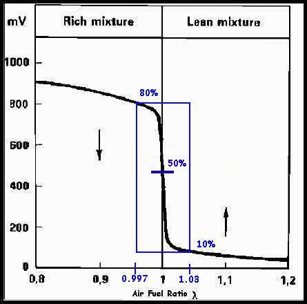
A readout of 50% AND an oscillating needle (engine running) indicates that all input signals and the Lambda
control system are ok. Readouts of 0% to 100% refer to particular fault source (see Fault Tables below).
On-Off Ratio Test Conditions for: Ignition ON
- Coolant temperature appox 80 deg C
- A/C Off
- Selector level in park 'P' position
- Connect ratio tester to Diagnostic connector (X11). Note this is NOT the X11/4 connector.
- Ignition: ON
- Engine: OFF
If any value other than 50% appears, refer to fault table for possible causes.
On-Off Ratio Test Conditions for: Engine at Idle and 2500 RPM
- Disconnect vacuum line at the Purge valve (Y58/1) and close it with a suitable plug for these tests.
- Coolant temperature appox 80 deg C.
- A/C Off
- Selector level in park 'P' position.
- Connect ratio tester to Diagnostic connector (X11). Note this is NOT the X11/4 connector.
- Ignition: ON
- Engine: Idle, then test at 2500 rpm
The needle should be at 50% AND should oscillate around that point (example: 42% to 55%). If not refer to fault table for
possible causes.
Fault Table: On-Off Ratio Test: Ignition: ON
On-Off
Ratio % |
Possible Cause |
Remedy ** |
| 0% |
Voltage supply from socket 3 of data link connector (X11/4) open circuit |
Repair harness |
| 10% |
Closed throttle position (CTP) recognition inactive |
Fuel Inj |
| 20% |
Wide open throttle (WOT) recognition active |
Fuel Inj |
| 30% |
Engine coolant temperature (ECT) less than 70 deg C or greater than 110 deg C |
Fuel Inj |
| 40% |
Not used |
|
| 50% |
Input signals ok |
|
| 60% |
TN-signal (rpm signal) or camshaft (CMP) position sensor signal not present |
Fuel Inj |
| 70% |
Starter engaged |
Fuel Inj |
| 80% |
CAN data exchange defective |
Fuel Inj |
| 90% |
Fuel safety shut-off active |
EA |
Fault Table: On-Off Ratio Test: Engine at Idle and 2500rpm
* Needle must oscillate if all monitored signals are ok.
** Consult the appropriate ECU Service Manual for further fault isolation tests.
On-Off
Ratio % |
Possible Cause |
Remedy ** |
| 0% |
Short circuit to battery in wire to data link connector (X11/4), socket 3 |
Repair harness |
| 10% |
CTP recognition applied constantly |
Fuel Inj |
| 20% |
Output of fuel injectors or one or more fuel injectors have open circuit |
Fuel Inj |
| 30% |
Engine coolant temperature (ECT) sensor (B11/2) faulty |
Fuel Inj |
| 40% |
Hot wire MAF sensor (B2/2) |
Fuel Inj |
| 50% * |
Oxygen sensor (G3/2) not operational or defective, open circuit |
Fuel Inj |
| 60% |
CMP sensor (L5/1) |
Fuel Inj |
| 70% |
TN-signal (rpm signal) |
Fuel Inj |
| 80% |
CAN data exchange defective |
Fuel Inj or EA or DI |
| 90% |
Vehicle speed signal (VSS) |
Fuel Inj |
| 95% |
Deceleration shut-off active |
EA |
| 100% |
No voltage at LH-SFI control module (N3/1) |
Fuel Inj |
|