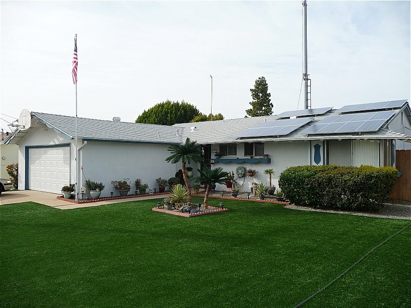
 San Diego has been fairly arid in the past few years. The rainfall totals are particularly low an my neighbor and I could see that
water restrictions were on the way to becoming 'law'. So we beat the rush and had artificial turf installed.
San Diego has been fairly arid in the past few years. The rainfall totals are particularly low an my neighbor and I could see that
water restrictions were on the way to becoming 'law'. So we beat the rush and had artificial turf installed.
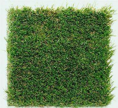
The project was started and completed by Forever Lawn in San Diego. The selling point was
the "look" of the grass. It has embedded "thatch", a brown colored grass. It looks real b/c that's what real grass does. I can add,
it's was one of the best things that we did since currently there's grass watering restrictions in effect!
|
 Both lawns were done together. This way a bobcat was used to remove both lawns in one 'scoop'. On my side, there was the remnants
of a large ficus tree. The roots were massive and although the tree had been removed a few weeks before, the roots that were
"unearthed' by the bobcat, totaled about 500+ lbs. This adds to the 2 tons of tree that was cut-down. The tree started to take
over my house, so it had to go!.
Both lawns were done together. This way a bobcat was used to remove both lawns in one 'scoop'. On my side, there was the remnants
of a large ficus tree. The roots were massive and although the tree had been removed a few weeks before, the roots that were
"unearthed' by the bobcat, totaled about 500+ lbs. This adds to the 2 tons of tree that was cut-down. The tree started to take
over my house, so it had to go!.
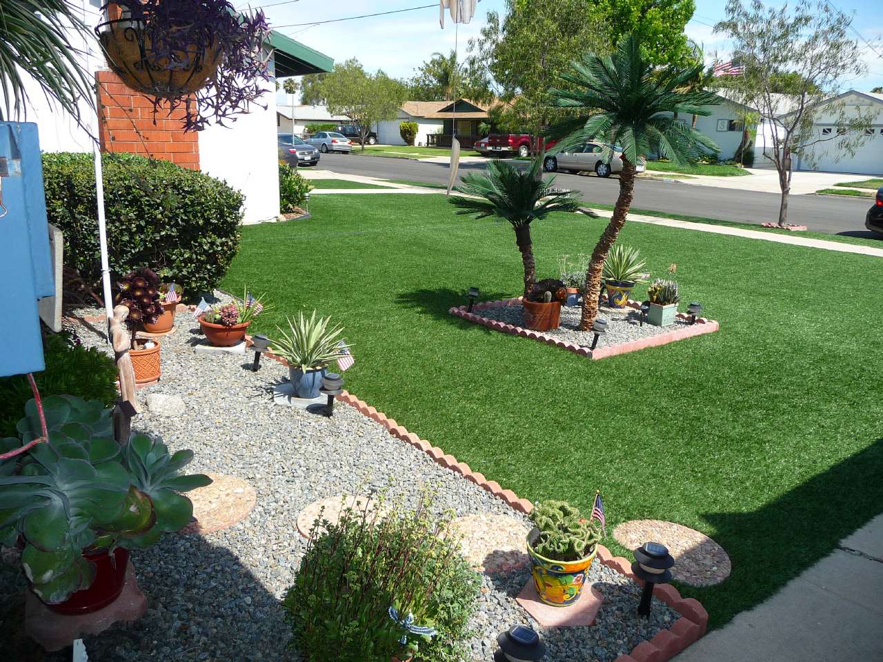
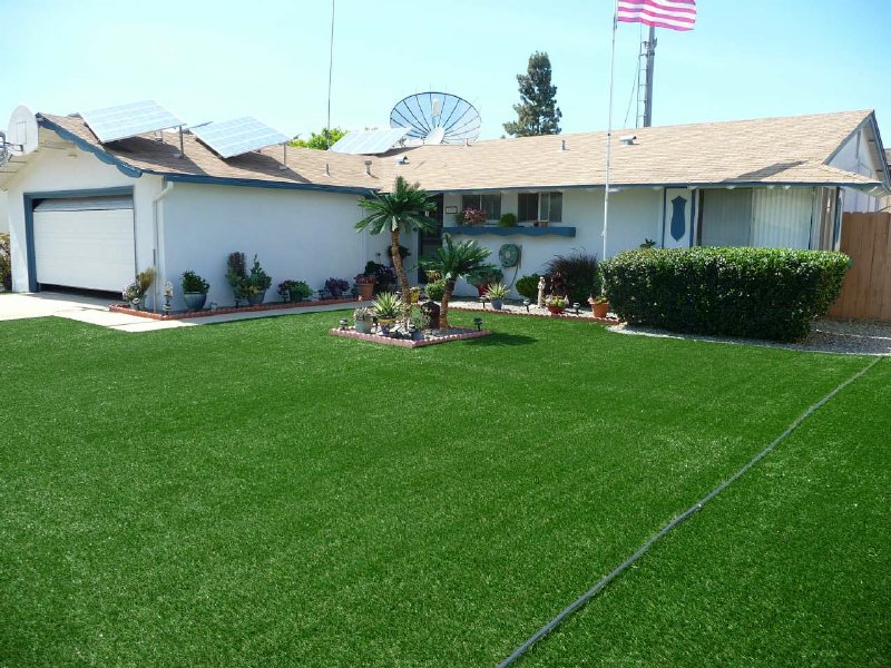
This is my favorite shot . . . shows the flower garden, the "island" and my neighbor's grass.
|
 My wife and I decided to specialize in low-water requirement plants and bushes. And we also decided to go with a "container garden"
concept rather than use the soil b/c this would allow us to better control the water usage. So you can see a collection of desert
plants and succulents that have thrived well here.
My wife and I decided to specialize in low-water requirement plants and bushes. And we also decided to go with a "container garden"
concept rather than use the soil b/c this would allow us to better control the water usage. So you can see a collection of desert
plants and succulents that have thrived well here.
|
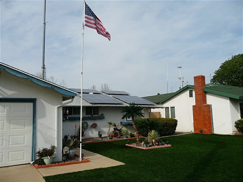
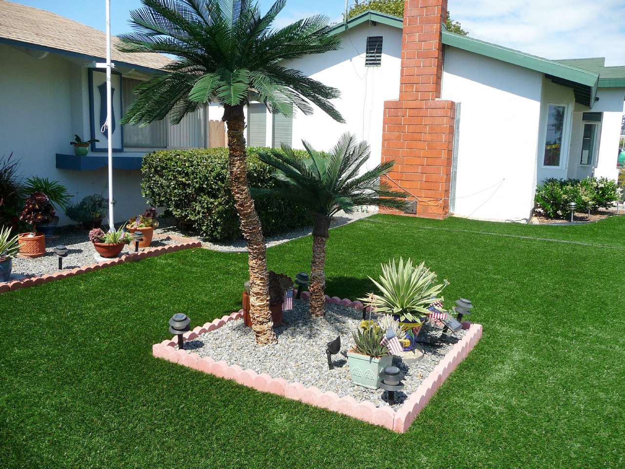 The "island" was my idea b/c I thought that the front yard would be too barren w/o a tree of some sort. But I didn't want another
'real' tree so while researching on the Internet, I found a site that builds neat palm trees using real bark. The inside is a
bendable metal tube and the tree comes in sizes from 3 ft to 15 ft in height. The 15 footer is $5000! I opted for a 6' and 3' with
different 'bends'. All in all, it looks pretty nice, IMO.
The "island" was my idea b/c I thought that the front yard would be too barren w/o a tree of some sort. But I didn't want another
'real' tree so while researching on the Internet, I found a site that builds neat palm trees using real bark. The inside is a
bendable metal tube and the tree comes in sizes from 3 ft to 15 ft in height. The 15 footer is $5000! I opted for a 6' and 3' with
different 'bends'. All in all, it looks pretty nice, IMO.
|
 This pic shows the 'grain' of the grass and it's extremely easy to 'clean'. I use a blower and collect the debris from birds,
blown leaves, etc and that gives me my "grass" maintenance exercise. The bushes to the far right are . . . "REAL"! Just so you
don't think that all is fake! The center island clearly shows in this picture and lighted at night by 16 solar lights w/ an
great amber glow at night.
This pic shows the 'grain' of the grass and it's extremely easy to 'clean'. I use a blower and collect the debris from birds,
blown leaves, etc and that gives me my "grass" maintenance exercise. The bushes to the far right are . . . "REAL"! Just so you
don't think that all is fake! The center island clearly shows in this picture and lighted at night by 16 solar lights w/ an
great amber glow at night.
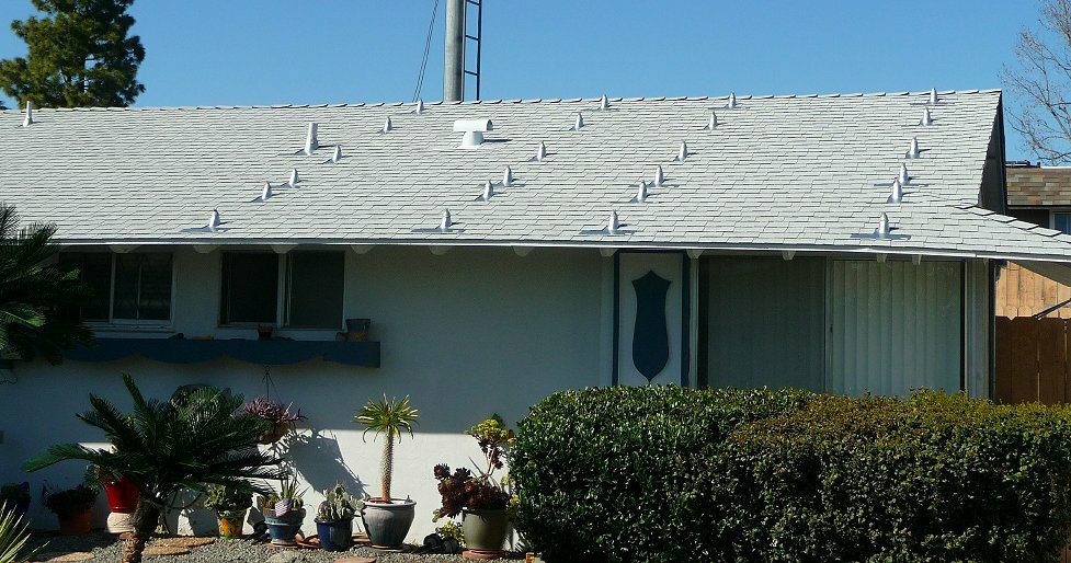
You can see (left to right), flag pole, HDTV OTA w/ mast, solar panels and ladder of my tower. I've removed four (4) small Ku
dishes and and one (1) C-band (11ft dia) dish. What a difference! There's still two (2) Ku band dishes but they're not visible
b/c they were mounted below the roof-line.
 Contrast this to the former picture showing the myriad of Ku dishes (4), C-Band 11ft dish and the solar panels mounted on the
garage roof.
Contrast this to the former picture showing the myriad of Ku dishes (4), C-Band 11ft dish and the solar panels mounted on the
garage roof.
You can see (left to right), the solar panels, HDTV OTA and mast, C-Band and Ku-Band dishes (4), flagpole
and the base section (with the ladder) of my tower.
|
 This is another favorite angle showing the my highlighted area with the backdrop of my neighbor's home. In the background
you see a large 'tower' . . that of the Verizon Wireless cell tower about two (2) blocks away.
This is another favorite angle showing the my highlighted area with the backdrop of my neighbor's home. In the background
you see a large 'tower' . . that of the Verizon Wireless cell tower about two (2) blocks away.
|
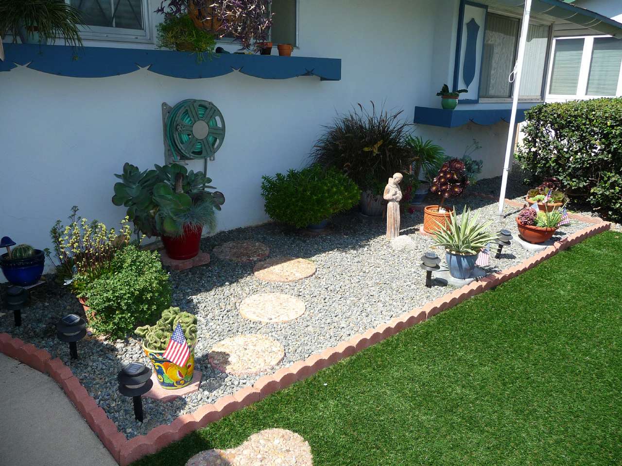
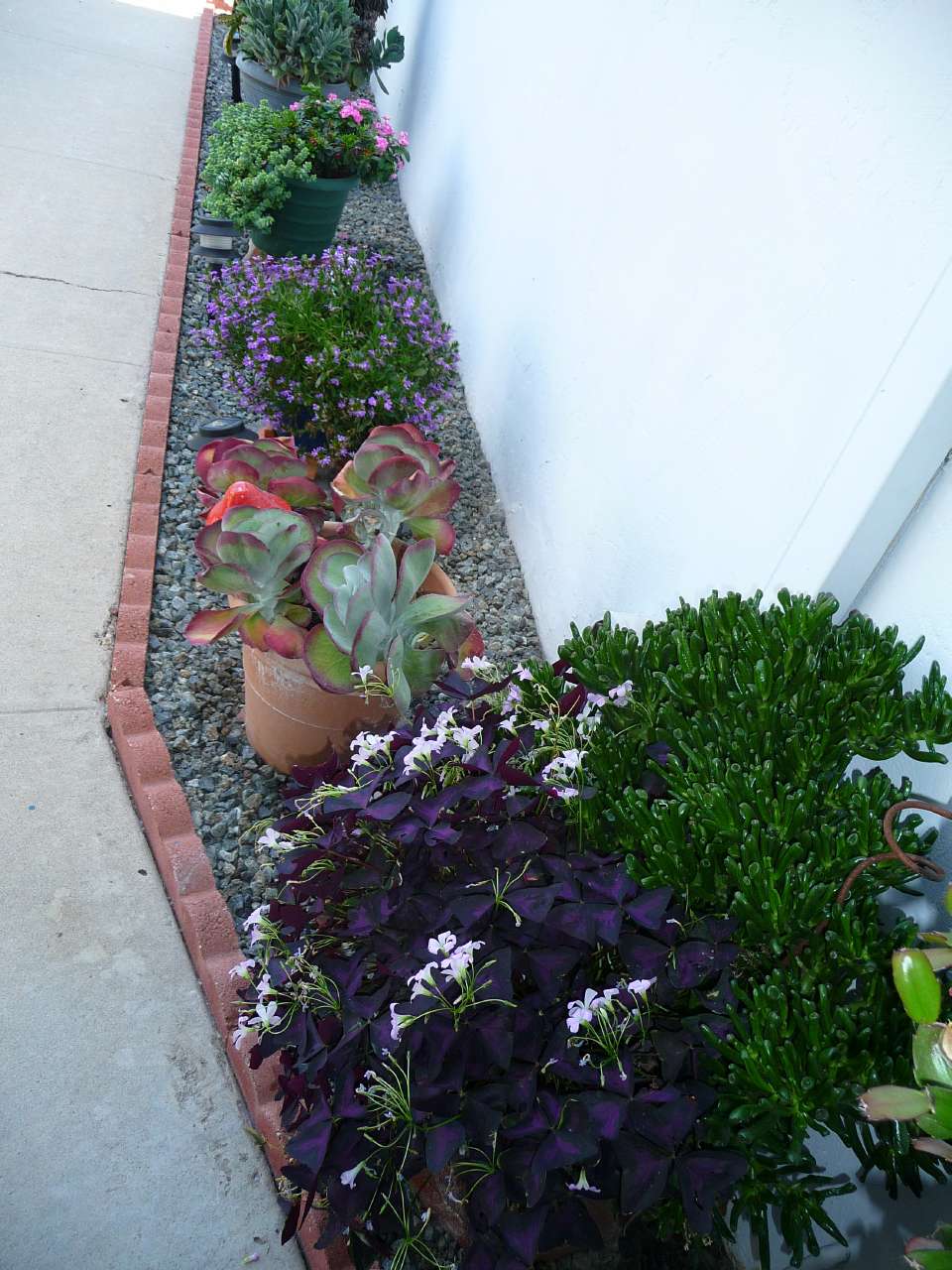 This pic shows the side of the house with some unusual plants. The foreground shows a purple Irish four leaf clover
with white buds that the humming birds just love. Every afternoon they stop by for some "lunch". One of these days
I'll get a good picture.
This pic shows the side of the house with some unusual plants. The foreground shows a purple Irish four leaf clover
with white buds that the humming birds just love. Every afternoon they stop by for some "lunch". One of these days
I'll get a good picture.
|
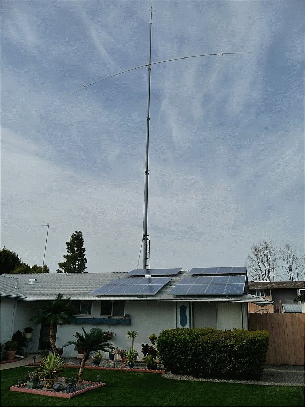 Since this is a HAM radio site, I can't very well leave out the "tower"! So here's shot from the front yard showing the tower
fully extended with the CD78 dipole at the 75 ft level. On the top is the G6-144 2mtr colinear antenna at 93 ft.
Since this is a HAM radio site, I can't very well leave out the "tower"! So here's shot from the front yard showing the tower
fully extended with the CD78 dipole at the 75 ft level. On the top is the G6-144 2mtr colinear antenna at 93 ft.
|
-- Solar System Update --
 The solar panels are made by Kyocera and are their "KC-120-1" panels, producing 120W under proper sunlight. These were completely
replaced last year b/c of 'solder' problem in the panels that showed under high temperatures of 100F. The solder would partially
melt and then reflow producing serious ohmic connections. So much so that the panel's output would be "millivolts" and "microamps"
of current. The company replaced all of them including the cost of removal and re-installation! That's a warranty!
The solar panels are made by Kyocera and are their "KC-120-1" panels, producing 120W under proper sunlight. These were completely
replaced last year b/c of 'solder' problem in the panels that showed under high temperatures of 100F. The solder would partially
melt and then reflow producing serious ohmic connections. So much so that the panel's output would be "millivolts" and "microamps"
of current. The company replaced all of them including the cost of removal and re-installation! That's a warranty!
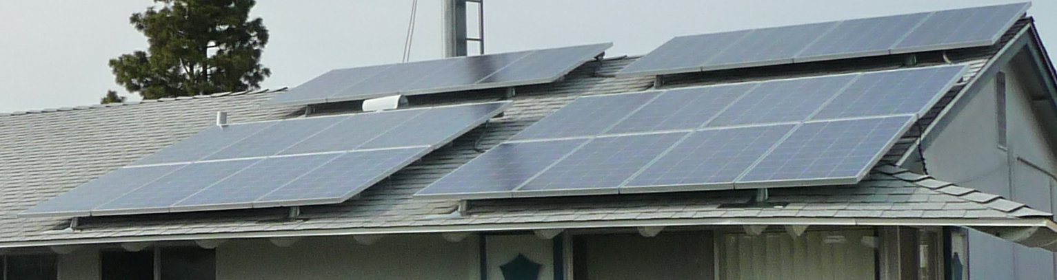
 The solar panels were moved from the garage roof to the east side of the south-facing roof after the new roof was laid. Prior to
the roof's completion roof jacks were mounted directly to the rafters prior to the roof shingles so that the jacks could be
properly sealed for water. Four (4) panels are mounted in a "rack" and requires four (4) roof-jacks to support each rack for a
total of 24 jacks.
The solar panels were moved from the garage roof to the east side of the south-facing roof after the new roof was laid. Prior to
the roof's completion roof jacks were mounted directly to the rafters prior to the roof shingles so that the jacks could be
properly sealed for water. Four (4) panels are mounted in a "rack" and requires four (4) roof-jacks to support each rack for a
total of 24 jacks.
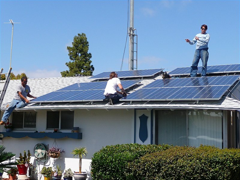 The pic shows the solar installation crew completing the rack and electrical wiring on the roof with Brad directing the work and
providing guidance to the crew members. He and his crew are expert in installing small to multi-kilowatt solar installations.
The pic shows the solar installation crew completing the rack and electrical wiring on the roof with Brad directing the work and
providing guidance to the crew members. He and his crew are expert in installing small to multi-kilowatt solar installations.
Contact info: Brad Hosmer of Adroit Solar. Phone: 858-483-3568 or via email
brad@adroitsolar.com
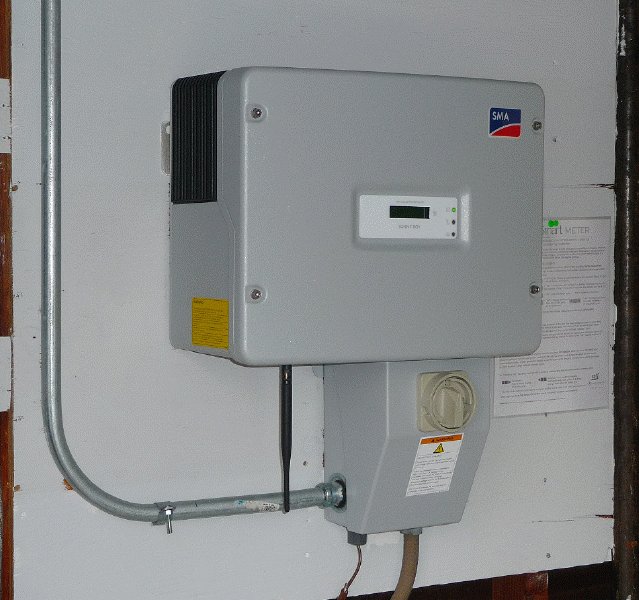 The original Trace Inverter solar system w/ battery backup has been replaced with a newer, more efficient solar system featuring
the SMA "sunny boy" series of inverters. This model, SB4000US features a 4000W capacity and 97% efficiency rating at 240V
usage. It directly handles high-voltage inputs (up to 600Vdc) and is tied directly to the solar panel's series output.
The original Trace Inverter solar system w/ battery backup has been replaced with a newer, more efficient solar system featuring
the SMA "sunny boy" series of inverters. This model, SB4000US features a 4000W capacity and 97% efficiency rating at 240V
usage. It directly handles high-voltage inputs (up to 600Vdc) and is tied directly to the solar panel's series output.
Also shown [black antenna] is newly released Piggy Back_Plus Bluetooth card system for remote communication with the SB4000 inverter.
This re-designed card mounts inside of the inverter while the outside antenna communicates via Bluetooth technology to the Sunny Beam
in my radio studio. Readout of current inverter parameters occurs every 5 mins.
Info on the
SMA SB4000 Solar Inverter
--- SMA 'USA' Bluetooth Problem ---
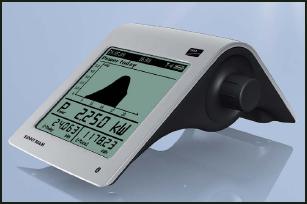 The problem, simply stated, is that the SMA specs for Bluetooth (BT) transmission range (apx 150') using the "BT piggy back" card communicating
with a "Sunny Beam" monitor device (shown in the pic) is materially shorter in the USA b/c of the use a "metal" cover (as shown in the SB4000US
picture). Europe uses a plastic cover so the signal is not materially attenuated.
The problem, simply stated, is that the SMA specs for Bluetooth (BT) transmission range (apx 150') using the "BT piggy back" card communicating
with a "Sunny Beam" monitor device (shown in the pic) is materially shorter in the USA b/c of the use a "metal" cover (as shown in the SB4000US
picture). Europe uses a plastic cover so the signal is not materially attenuated.
The BT range is cut to about 40' (depending on number of wall/doors that the signal must penetrate) for reliable range b/c of said cover.
Measurements show -21dB loss. The loss of that much signal materially reduces the range of the device. That's it in a nutshell.
To give you some perspective, -21dB represents a signal loss of 126 times! So if you started with 100mW signal, it would be reduced to
0.8mW or 800uW. . . that's 800 micro-watts! It's easy to see that much loss can't be tolerated.
The SMA solution is to purchase a BT repeater unit at the cost of apx $500+. It remains to be seen that this solution really
does increase the BT range. For me, that's not particularly attractive solution since, 1) I don't know that it will materially increase the
BT range and 2), the cost is really ridiculous.
--- K6JRF Interim Solution ---
SMA has informed customers that they are working on a retrofit for their BT card, called the "BT Piggy Back PLUS" card. This will solve the
communication problem of transmitting through "metal", so in the meantime, in order to have communication with my SB4000 inverter, I've come
up with this simple solution.
One solution which is immediately obvious, is to replace the cover with a "plastic" material that would be transparent to RF. And SMA
offers such a cover . . . in Europe . . . but will not allow USA SB inverter owners to use that solution. I spent time going around
this with USA SMA personnel to no advantage. Of course, you could have a "european" friend buy it and send it over to you. That would
work nicely . . . if you have some friends there. I do but have added that solution to the back-burner as a last-resort solution.
The SB inverter's NEMA rating is primarily accomplished via the "covers", the back and front including the gasket seals that
prevent the "elements" (water, ice, wind, dirt, etc) from gaining access to the inside electronics. For many residential users,
the NEMA rating is overkill! If the metal covers were replaced w/ an RF transparent material (plastic for example), the unit
could still have a NEMA rating, albeit lowered, but would allow the Sunny BT card to communicate over the originally intended
distance of 150 feet.
The SMA inverters in Europe are delivered with a "plastic" cover so they are RF transparent. So using that as a starting
point, I bought a plastic "tray" that would take the place of the existing cover and the RF loss problem should be solved.
So that's exactly what I did and here is how to duplicate it for yourself.
A word of caution! The overall packaging of the SMA inverter with its cover gives it a NEMA 3* rating. So,
it's a very rugged unit ready to mount outside in the elements. But many have it mounted INSIDE of a weather tight
environment where the worse that can happen is some cold temps in the winter or hot temps in the summer! Both are my situation,
so using a plastic cover should not be a problem. This plastic cover still prevents the elements described below from gaining
access to the electronics but not fully in the manner of the original cover. But, because of where the SB is mounted, it doesn't
have to!! YOUR ENVIRONMENT MAY BE DIFFERENT so beware that this solution necessarily may not fit all cases!
*
Enclosures constructed for either indoor or outdoor use to provide a degree of protection to personnel against access
to hazardous parts; to provide a degree of protection of the equipment inside the enclosure against ingress of solid foreign objects
(falling dirt and windblown dust); to provide a degree of protection with respect to harmful effects on the equipment due to the
ingress of water (rain, sleet, snow); and that will be undamaged by the external formation of ice on the enclosure.
My plastic cover meets those reqts except wind driven rain and ice formation. So I guess it's not that bad after all . . plus
it's RF transparent!
 I purchased this cover (fiberglass) from a USPlastics for apx $31. The size, as stated, was 17.75" W x 14" L x 4" H. That's just about
perfect dimensions where a cover of that size could be made to fit nicely. The walls/floor are 1/4" thick and it's very rigid.
I purchased this cover (fiberglass) from a USPlastics for apx $31. The size, as stated, was 17.75" W x 14" L x 4" H. That's just about
perfect dimensions where a cover of that size could be made to fit nicely. The walls/floor are 1/4" thick and it's very rigid.
As received, the inside dimensions were not as advertised but much different - 15.5" W x 11.5" L x 4" H - at least H was correct!
So the cover doesn't fit as I had envisioned but it does fit "OK" as the picture shows.
 There's a plastic "window" that is barely visible from the front angle. The good news is there's no appreciable attenuation with cover on, so
the -21dB signal drop due to the metal cover is now history and the BT range is adequate throughout my home. Even works in my HAM radio-studio
which is at the end of the house. Very pleased . . . for only $31.
There's a plastic "window" that is barely visible from the front angle. The good news is there's no appreciable attenuation with cover on, so
the -21dB signal drop due to the metal cover is now history and the BT range is adequate throughout my home. Even works in my HAM radio-studio
which is at the end of the house. Very pleased . . . for only $31.
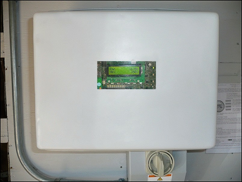
This is nothing fancy about it but it's solid complete w/ a 'front-window' for viewing of scrolling parameters. It works and keeps non-qualified
people from playing with dangerous 'toys' they know nothing about.
Nov 15,2011, my "Interim" solution has been retired in favor of the "Final" solution detailed below.
--- SMA Final Solution ---
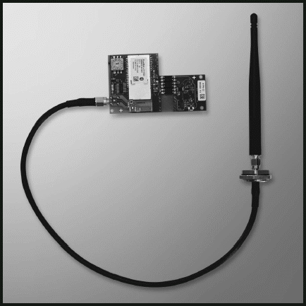 On Nov 14, 2011, I received the new BT PB-Plus card. The BG PB_Plus card allows you to establish a connection via the
SMA BT wireless technology to other SMA inverters and communication products with SMA BT such as Sunny Beam with BT.
On Nov 14, 2011, I received the new BT PB-Plus card. The BG PB_Plus card allows you to establish a connection via the
SMA BT wireless technology to other SMA inverters and communication products with SMA BT such as Sunny Beam with BT.
As the picture shows, it consists of a main PB board that has been re-designed to accept an SMA output connector, coaxial cable that connects
the output BT amp with the radiating antenna. This antenna mounts outside the metal case so the -21dB loss s/b eliminated.
It's very easy to install and the detailed manual shows the steps required to complete the installation.
I installed it during the during the evening hours when the system shut down. This is the easiest way since the inverter is off so removing and
re-installing the new PB_Plus card is literally plug-and-play. Since the power is off, there's no shut-down or bring-up procedures needed.
All you need so is set the ID to your previous setting and the Sunny Beam will automatically re-sync when the sun comes up. If done when the
inverter is 'sleeping', it takes about 15 mins max.
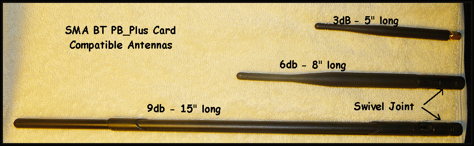
I have, over the years, collected a large array of various WiFi antennas that are compatible with the PB-Plus card's output SMA connector. The
picture shows two of them in contrast to the supplied antenna (3dB).
The nice feature about the 6dB and 9dB antennas is that they both can swivel 45 and 90 degs with a detent at each position. Since the DC Connect
module is metal it should materially perturbate the pattern leading one to think that a 45 deg (or 90deg) angle would give cleaner and stronger
signal distribution.
The supplied 3dB antenna is 5" length, the 6dB antenna is 8" long and the 9dB tops all with its 15" length. I used all three for testing and
found that best overall choice was the 6dB model. Being only 3" longer than the stock antenna, it makes the best choice b/c of its length
compared to the 9dB antenna. However, as shown below, the 9dB has the best performance of the three.
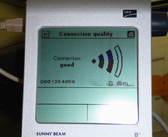
The signal level is outstanding in the radio-studio as the picture shows. With my "cover" mod, the typical signal level was -76dB as shown
here.
With the PB_Plus card and the 6dB antenna, the level is -71dB* . . . an increase of 5dB in the studio! Of
course, that's with the original cover in place!
Note: My "cover" mod (see above) showed that my SMA SB4000US inverter is installed in a weather-protected environment. The worst that happens is
a little COLD or a little HOT! There are NO water problems. With that said, be warned that the two antennas specified are NOT necessarily
waterproof. The antenna's knuckle joints can't be watertight b/c they bend. Water can and will get into that joint if your inverter is outside.
You should use at your own risk! The supplied 3dB antenna is watertight due to its construction.
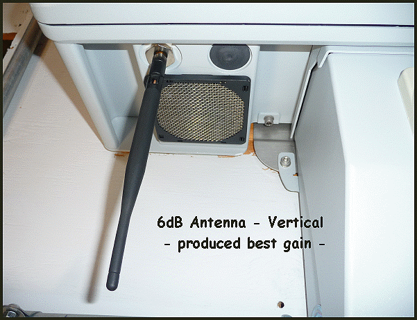
The DC Connect module attached to the SB4000 inverter did not cause pattern-skew as I suspected. The signal level in my studio was higher w/ the
antenna in a vertical position than the picture below shows for the 45deg tilt. I did not take time to rotate the angle to see if there was an
optimum point.
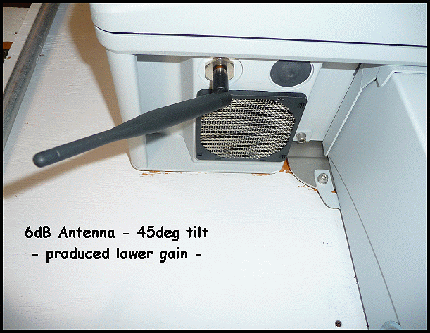
This picture shows the longest [15"] 9dB gain antenna in use. It has higher gain (apx 3dB] and produces more signal level in the radio
studio. I've consistently see signal levels of -68db on the Sunny Beam. As the picture shows, the antenna
almost rests on the cabinet's top cover which makes it a bit too long for my tastes. But it does seem to outperform the other two antennas!
Suggestion: No matter what external antenna you use, if your inverter is mounted OUTSIDE, use a dab of silicone gel on the antenna's connector
just as the "cable-guy" does. This will seal it from water penetration. If water gets into that connector, you WILL loose signal and you
COULD blow the PB_Plus card output stage. A word to the wise.
It appears that SMA did listen to their customer's problems and got the job done correctly. They have come up in my eyes as being responsive to
fixing problems w/o any extra cost to the customer. This new PB_Plus card is a shining example.
* All of the readings fluctuate and you can expect 2dB or so variation.
Info on the SMA Bluetooth PiggyBack Plus Card
--- Sunny Beam External Antenna Modification ---
All HAMs know that the "antenna" is key to signal reception as well as signal transmission. So wanting the best signal possible, I made some
embellishments to the WiFi antenna to increase the signal level into my radio studio. I also modified to the Sunny Beam to add an external
antenna, the main emphasis of this section.
The basic problem is that my garage is a jungle of cars, pipes and wires. Add to that the number of walls it needs to get through, getting a
good signal on the far end of the house, into my radio studio, is problematic.
One of the easiest ways to increase the gain of any WiFi antenna is to add a parabolic reflector. All you need is some tin-foil, cardboard,
styrofoam and a glue gun to paste it together. The picture shows the field when a reflector is added; more forward gain and less signal off
of the back side.
The template for making the reflector can be found here
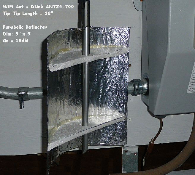
Using another of my WiFi antenna arsenal, a DLink 7dBi vertical, I made a 9" x 9" reflector using the above materials. It's easy to build and
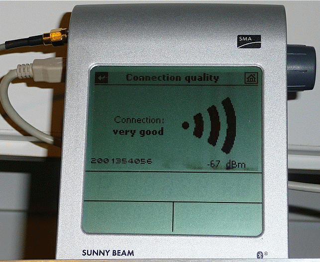
it works! The picture shows the front view of it mounted to the bottom of the SB4000US inverter. It's 'boresighted' to the far side of the
house (thru 5 walls at less than 45deg angles!). It does work since the signal level is as high as -65dB, typically it's no worse than
-67dB as measured on the Sunny Beam. Note the all "FOUR" bars are active and the signal is "VERY GOOD". That's worth the price of
admission alone.
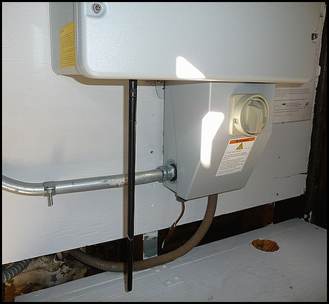
I next modified the Sunny Beam to accept an external antenna b/c of the shielding caused by the many metal cases of my radios and ancillary
equipment. Where I wanted to put the SB, turned out to be the worst spot! Of course, that is Murphy's Law! Signal levels were -78 and lower.
To modify the unit, remove the batteries and remove the bottom cover. Drill a 1/4" hole for the RP-SMA female connector and attach with a
'tooth' washer to make sure the connector doesn't "rotate" when the external antenna connector is attached. The picture shows the details.
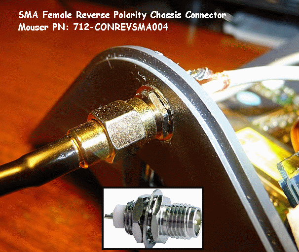
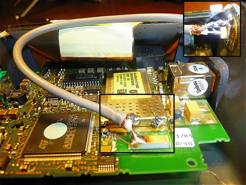
Next you need a 4" length of mini-coax; solder it to the SB BT output stage (copper 'antenna') and the shield to the BT case as shown. Next
solder the output side to the SMA RP connector as shown. Use a file to rough-up the supplied nut so ensure good solder flow to the shield.
The external antenna is connected through about 4ft length of coax, mounted on a cabinet top to get the best signal reception possible from
the inverter. You now have a very sensitive Sunny Beam rcvr that can be mounted anywhere you wish and still guarantee "perfect" reception
thanks to the external antenna input. Of course, you can use it w/o an external antenna or with a shorter direct-mount antenna.
This may not be needed for those with less obstructions in the signal path. In any event, with very little effort, you can increase your BT
signal and cut down on potential interference.
|
|
 Long story shortened, the new camera is a Panasonic Lumix DMC-TZ50. Coming from the "Mavica", it's like stepping
into a Maybach after driving a VW bug! This new camera takes pictures automatically that I used to spend hours trying
to take w/ the Sony.
Long story shortened, the new camera is a Panasonic Lumix DMC-TZ50. Coming from the "Mavica", it's like stepping
into a Maybach after driving a VW bug! This new camera takes pictures automatically that I used to spend hours trying
to take w/ the Sony. 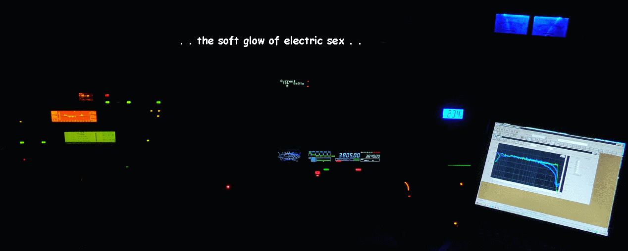 Here's another picture I took by night with the soft glow of . . . LEDs and LCD screens . . . there's lots of them in
use today. It's the "tube" that's in short supply. Click picture for larger size.
Here's another picture I took by night with the soft glow of . . . LEDs and LCD screens . . . there's lots of them in
use today. It's the "tube" that's in short supply. Click picture for larger size.