|
K6JRF's Page formerly W6FZC AL-1500 Linear + "Lazy Susan" + Blower Noise + 8877 Tests |
(Updated: Dec 19, 2020)
 Recently, Bruce WD4NGB was interested in my mods to the AL-1500 linear. He has a AL-82 that is almost identical
except for 3-500Z tubes otherwise the control ckts are identical. He likes to operate high-power digital mode and the
linear gets warm -> hot!
Recently, Bruce WD4NGB was interested in my mods to the AL-1500 linear. He has a AL-82 that is almost identical
except for 3-500Z tubes otherwise the control ckts are identical. He likes to operate high-power digital mode and the
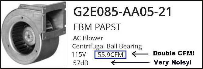
linear gets warm -> hot! He asked if I knew about a blower 'dropin' that has more CFM. Checking the Pabst blower spec showed there is a version with double the CFM output: G2E085-AA05-21 and, unfortunately, double the "noise"! He plans on purchasing this blower, modifying the linear with the mods shown in the link below: He sent some info and link to his page showing the work to date. If you operate in a similar way, I recommend that you follow his 'adventure'. Direct Link: here If you have any questions about the details, please contact Bruce directly: wd4ngb@charter.net 73, Jim K6JRF |
 A few months ago, Clint WA6TMJ corresponded re my mods to the AL-1500 linear. He was interested in them and wanted
something similiar . . . but this time add a "bigger" transformer to give the linear some added "head-room"!
A few months ago, Clint WA6TMJ corresponded re my mods to the AL-1500 linear. He was interested in them and wanted
something similiar . . . but this time add a "bigger" transformer to give the linear some added "head-room"!
He sent some pics and a brief writeup so I've added this info into the referenced WORD file for your reading pleasure. I strongly recommend that you d/l the document and enjoy the reading of his success. Direct Link: here Transformer PDF: here If you have any questions about the details, please contact Clint directly: wa6tmj@arrl.net 73, Jim K6JRF |
|
This page shows the pictorial highlights of installing a new AL-1500 linear amplifier.
That in itself is not unusual but the way I mounted it, is! Borrowed the concept of a "lazy susan" and used that to
hold the new amp. Next the blower noise was attacked and considerably attenuated. A blower alternate is being explored.
Finally, the tube was tested in two linear amps and the results shown in an graphical format.
|
|
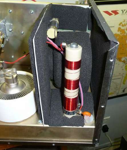
Lazy Susan: I used a sheet of plexiglass (P/G) that was surplus from my "Add an A/C to a Humidor" project. It became an "insulation" layer in order to decrease the heat loss through the glass top of the humidor. But that's another story. The P/G was cut 17" x 17" square since the AL-1500 rubber feet dimension are apx 16" square. So 17" x 17" would be more than enough to hold the amplifier w/o having the P/G extend to far. The picture shows the "bare" AL-1500 mounted on it and turned about 45 degs in preparation of mounting the power transformer.  The linear was lifted onto the L/S in this condition b/c it only weighs about 35lbs. This is the LIGHTEST that the amp will be b/c the transformer and 8877 will take it to about 88lbs. The L/S gives full access to all parts of the amplifier by simply turning it. The Teflon chimney is a full face mount completely covering the tube and it forces all available air to funnel up the tube's heat sink fins. This chimney is courtesy of Larry, W3OZ. Tnx, again! The plate cap attachment has been loosened and lifted so as to not interfere w/ the tube's mounting. After the tube is properly seated and the Teflon chimney is aligned and closed to the bottom of the tube frame, then the plate cap is attached. This picture shows the linear from the right side.  The picture shows the Peter Dahl transformer mounted inside the AL-1500 w/ all leads connected to the proper terminals for 240Vac operation. Note that it was turned on the L/S and was completely accessible with very little effort.  Sound Proofing the Amplifier: The blower noise is due to the bearings in the motor which produces a low 'rumble' and the squirrel cage that produces a higher pitched whine. To lower the blower noise level, sound proofing material was purchased and added as you will see. The material used is shown at the end of this section and I do recommend it since it has self-stick backing making it very easy to apply. Second, it's reasonably priced and available here in So Cal. Top Cover: The picture shows the inside of the top cover w/ the soundproofing material added. There's no need to take "precision" measurements. Just make sure you leave enough room for the inside and outside "rails" and the tube's mounting "box". Follow the picture as a guide as to where to add sound material. It must be clear for 4.5" as measured from the back screw holes and 4" from the tube mount.. This will allow the cover to fit over and around the blower cavity. This also isolates the cover from the main frame which is very important! Also be sure to use ALL of the screws to fasten the cover! 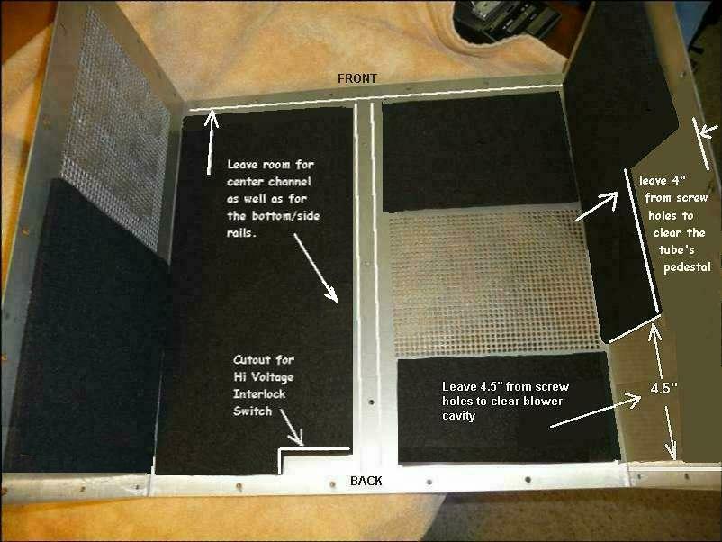
The main amplifier section does not need any sound proofing material except for the blower cavity area. The now-padded cover materially absorbs the sounds coming from the amp. The sound material was added to the front side of the 'plastic' barrier b/c of the hi-voltage fuse, plate choke and hi-voltage wiring. Later I added some to the inside of the barrier. 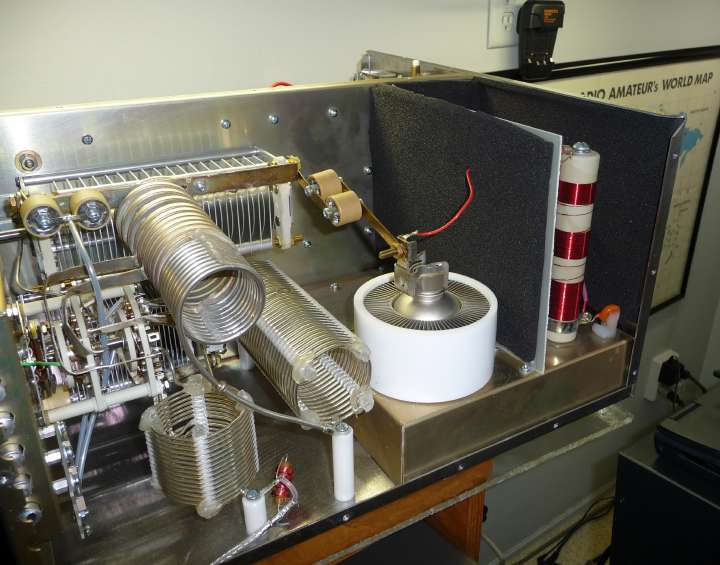
|
|||||||||||||||||||||||||
|
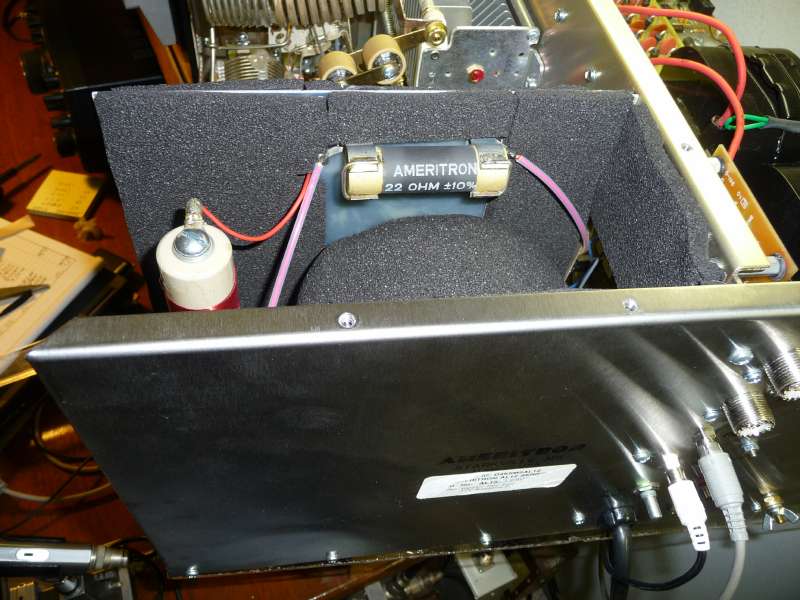
The blower "cavity" is where the sound gets amplified due to the hard surfaces acting as a reflector. Add as much
sound material as you want and can squeeze in. Even the "floor" can be dampened, you can't have too much! Make sure that the
blower is mounted on a 'rubber' insulator in order to isolate the blower's vibration from the metal chassis. The part is
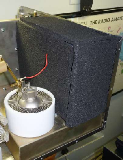
available from Ameritron. After completing the inside, the 'breakthrough' was the "house" that was built by adding top and side covers as shown in right picture. This turned out to materially attenuate the blower noise and vibration so much so that you actually have to listen to hear the blower!! Sound Material Source: I've purchased other sound dampening material from this company in the past. They have a large supply of most every type of "sound" material including sound absorbing paints! For this task, I used the 1/4" thick version shown in this link. The manufacturer's product number is "09-42720-PSA" currently priced at $13.50/ft for 1/4" thickness. PSA stands for "pressure sensitive adhesive" on the back side of the material. This is available in 48" widths, so you only need 1 ft . . actually less but it's good to have around. The self-stick backing makes it very easy to apply to do the job correctly and, to boot, neatly! I used about 90% of the 48" width for this project. The page shows all of the various thickness's from 1/8" to 2". The 2" thickness was used in the cigar humidor A/C project. Comments: The sound material has reduced the blower bearing noise by about at least 10 - 12dB but there's some residual noise coming out directly from the top air outlet. 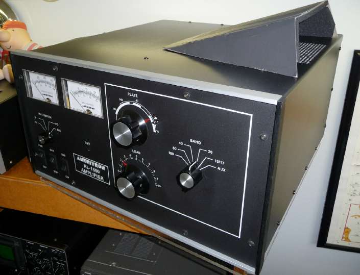
This noise can be further attenuated by adding a 'baffle' over air outlet port. This concept was used on the AL-572 and it further reduced radiated noise. A baffle is made by using folded cardboard lined with the 1/4" sound absorbing material as the picture shows with the air inlet and outlet baffles in place; painted flat-black to blend w/ the linear's color. Make sure to make them large enough so that the air flow is not restricted. The baffles are not pretty but they do take another 3dB of noise away. In my case, the amplifier is less than 2 ft from the mic so more than normal amount of attenuation is needed. When the audio system's 'gate' is opened and the transmitter keyed with an open mic, there was no power output as shown on the wattmeter. The noise level heard in the headphones was almost non-existant. The linear amp now has an extremely low blower noise level, so the project was a definite success. Overall the noise is considerably lower (18 dB) so it was worth the time and few $$ of material. I do recommend it for those trying to keep the audio noise as low as possible for a studio type audio system. Received an email from Larry, W3OZ who writes: The results are almost exactly as you have described. Putting my SPL meter on top of the amp I measured a 12 db improvement. The reading at my microphone was 5 db. The resolution of the meter on my SPL meter is not very fine, but that is the best I can do. If I put the intake and exit baffles on as you did I may find even more improvements. I am concerned that that mod my restrict the air even more. I do not want to damage my tube. But all and all I am happy with the mod and would recommend it. Received an email from Murray, K3BEQ that said: Finally soundproofed the 1500 based on your article and photographs. Although not as neat as your installation we managed to install the soundproof material as best we could. After the install I turned on the amp and did notice a reduction in noise and received reports from "don't hear any fan noise to "yes there is fan noise but not too bad". It seems the reports of some noise are only from those stations hearing my signal at S9 plus plus which is understandable. Thank you so very much for your detailed post on the soundproofing. Much appreciated. Tnx to both of you for doing the mod and writing me about your results. I, too, recommend this to all AL-1500 owners concerned with blower noise. Hard to go wrong for a few minutes work and 10 This picture shows how the linear appears from my operating position. It looks like it's floating off the top shelf. With the amp turned as shown, it is very easy to see what the meters are "saying". 
Blower Speed Settings:  Many have been concerned about using the LOW speed tap to decrease blower noise. As AL-1500 owners will attest, the
blower on M HIGH (factory default) is extremely noisy. Some say they have to leave the shack!!
Many have been concerned about using the LOW speed tap to decrease blower noise. As AL-1500 owners will attest, the
blower on M HIGH (factory default) is extremely noisy. Some say they have to leave the shack!! In addition, the AL-1500 User Manual states that you can connect to the LOW setting and be assured that is enough cooling for SSB and CW operation.  The chart shows that for proper 8877 tube cooling, 38CFM under 1500W anode dissipation would meet that requirement at sea-level. It's interesting that the 3CPX1500A7 requires a little less cooling (35CFM) but has more power dissipation. Not quite clear why?  Using my Mastech Digital Anemometer (MS6252A), the air-exit opening was entered into the instrument: 7.5" x 5.5" yields 0.286 sq ft. This instrument then computes the air flow in CFM (cu ft/min) and displays the results. It showed a range depending on where the anemometer was placed in the opening. Keeping the "Air-Deflecter" [AD] in place was reasoned to be the most accurate. Placing it directly in front as the picture shows allows the anemometer to catch (most) all of the air being moved. Results showed 72.7 CFM. If placed directly over the top of the 8877 tube the air flow measured 93.8 CFM. Both measurements meet or exceed all cooling requirements for 8877 tube in ICAS operation. So there's no need to worry about using the LOW speed tap for AL-1500 operation. |
|||||||||||||||||||||||||
|
Blower Alternates: I contacted ebmpabst re the AL-1500's stock blower, G2S085-AA19-15 to see if something couldn't be done to the existing blower to "quiet" by some custom operation. That doesn't appear feasible. The complete specs for this fan are here. Click on the PDF document for details. In an email reply from a ebmpabst apps engineer, the 8506N tubeaxial fan was recommended. However since it's only only has a 3dBa lower noise figure than the original, it's wouldn't be a replacement candidate. Later, in another email, the 3806 was recommended. This looks like a possibility. The 3806 specs [as well as all of the "3000" series axial fans] are here and the chart below shows a summary for both blowers. 
The 3806 tubeaxial fan has greater CFM (Eimac recommends 29.5cfm @ 1000w plate dissipation) and this one will do 35.3 and it only has 29dBa noise. That's a 9dB reduction which is close to the design goal of a 10dB difference. Also the size if 92mm x 92mm (3.65" sq) so other than having to enlarge the hole (the down side), it will provide better air flow, thus improved cooling to the tube. A positive up side! The maximum size that would fit is apx 3.75" so this fan meets that criteria. One thing to remember; the lower the fan's rpm, the lower the noise! This fan's has 2150 rpm so that's why it's lower than the G2S085 at 3200rpm. Considering the access hole difficulty, I'm not sure that it's worth the trouble esp since the sound proofing has significantly reduced the noise level. So, at this writing, there isn't a drop-in replacement but there is a fan style replacement reguiring some "metal-cutting" mods. As of today, I've not tried this nor has anybody written that has done the fan replacement. The 3CX1500A7 tube (8877) that was purchased with the AL-1500 has an Eimac date code of "0536" indicating the tube was manufactured in 2005. That tube was, for me, the newest tube I've ever tested! Since this linear is only a few years old, it should be capable of a large "reserve" power, so I thought! The AL-1500 was sent to Ameritron for "cleanup"; first, remove the QSK board that was installed that didn't work properly. The previous owner "wired" around it rather than remove it. Second, have Ameritron install an EBS (Electronic Bias Ckt) board. As you have read, I firmly believe in the concept since why waste power when nothing is happening! The chart shows the 8877 testing results in the homebrew linear, my "Henry 4K". It has a massive power supply running 4100V @ 1.5amp so it has a large power reserve. AL-1500 on 220Vac Tap: Today, I checked the 240Vac line voltage and, with most of the radio/accessories powered by 240Vac, the line voltage measured 229Vac. So I re-wired the AL-1500 transformer to use the "green" tap (220Vac). The static output plate voltage increased from 3500Vdc to 3850Vdc, however, the xformer's output current limits at 950ma and is the main factor as the table shows. The available current reaches a plateau between 55 and 65 watts of input drive. So the transformer appears under-powered. 
As you see looking at the "Henry 4K" test results (BLUE curve), the tube appears capable of producing large amounts of power but when tested in the AL-1500, it appears to plateau very quickly as if it were an older, well-used tube. Such is not the case.
This chart details the test results with 220Vac plate transformer tap. Running the amp this way produced a small power output increase but the current capability of the transformer is still the limiting factor as the table shows. AL-1500 on 220 - 239Vac Filament Tap: The AL-1500 was returned to the factory-default 240Vac wiring. Then after a converstion w/ Ameritron's tech, I measured the line voltage and found that it varied from 232Vac at no load to 226Vac at full loading. Loading consists of most of the radio equipment in the shack, namely the FT-2000D, YO-301 scope, AL-1500 and TS-711 transceiver. Then the FILAMENT ckt was put on the 220 - 239Vac tap since the line voltage is TRULY low. The results are shown by the "AQUA" colored chart line. As you see, there's a slight increase in the output power for "low" drive levels (25W and 35W) but the guickly saturates at higher drive levels. Conclusions: So even though the transformer output voltage increased (by 10% for the 220V tap experiment and the 230Vac filament experiment) , there's really no significant increase in power output. The puzzling part is that Ameritron "specs" the following:
When asked if any AL-1500 amps do that, the answer was ". . . very few, if any."! The conclusion is the simple fact that the AL-1500 is a bit short in reserve power which points to the key power supply element, the plate transformer. |
|||||||||||||||||||||||||
 According to the P Dahl specs for the " . . .-1D", the output is 2570Vac @ 1amp producing about 3600Vdc of plate voltage
with a 240Vac line. Even at 1500W full output, the plate voltage shows 3100V @ 0.87amp and is at its limit.
That's why the power output of appears to saturate at 2000W at any of the test conditions I've employed.
According to the P Dahl specs for the " . . .-1D", the output is 2570Vac @ 1amp producing about 3600Vdc of plate voltage
with a 240Vac line. Even at 1500W full output, the plate voltage shows 3100V @ 0.87amp and is at its limit.
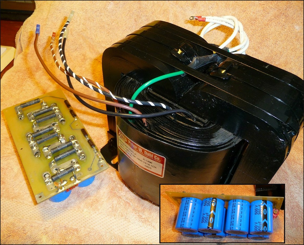
That's why the power output of appears to saturate at 2000W at any of the test conditions I've employed.Recent Updates: This section details the progress to date . . . [click all pics for a larger view] The 'correct' solution is to replace the present xformer with one made by Harbach Electronics. This features 2800Vac @ 1.5amps output, PN "406-1418-1DX". The picture shows the new, freshly built replacement transformer by Jeff, W8CQ wired w/ plugin connectors ready to be mounted. |
|||||||||||||||||||||||||
Obtaining 500V rated caps is not as easy as one would think! The new xformer will produce around 4000Vdc so 500V rated caps are needed
unless you live dangerously. Many vendors 'say' they stock them but you need to order a qty of 100 and then it will take 3 months to get
them. 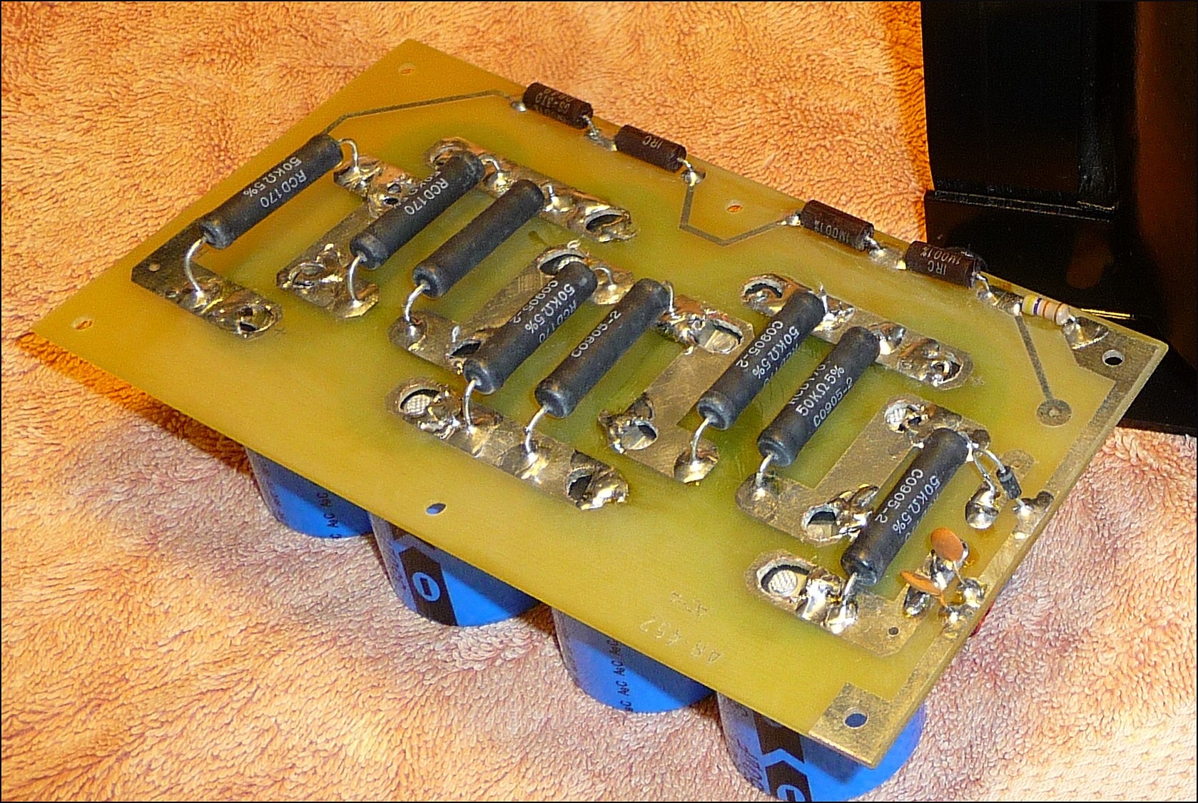 I found a ready source here for 350uF, 500V aluminum caps with 1-3/8" diameter. The
site is called "Just Radios" and they have a large stock of electronic parts for radios, new and old.
I found a ready source here for 350uF, 500V aluminum caps with 1-3/8" diameter. The
site is called "Just Radios" and they have a large stock of electronic parts for radios, new and old.The pic [click to enlarge] shows them mounted on the HV Cap Board along with the bleeder resistors and misc interface resistors and diodes. The board has 3/16" holes at 1/2" spacing for screw-style-mounting capacitors. The holes had to be enlarged to 5/16" dia so that the offset 'solder-tab' connections of the new caps could be made to fit properly. Electrically, the new HV Cap Board is identical except for the cap values. This board will safely operate up to 4000V while the present board is only good to 3600V. |
|||||||||||||||||||||||||
The new meter face was completed using "LabView Pro V2.1" in the "bmp" format starting from a large photo (10 Mpixels) taken w/ the
DMC-TZ50. Then it was reduced and inserted into a new AL-1500 Multimeter (M1 in the schematic). Looks pretty good.
[click to enlarge]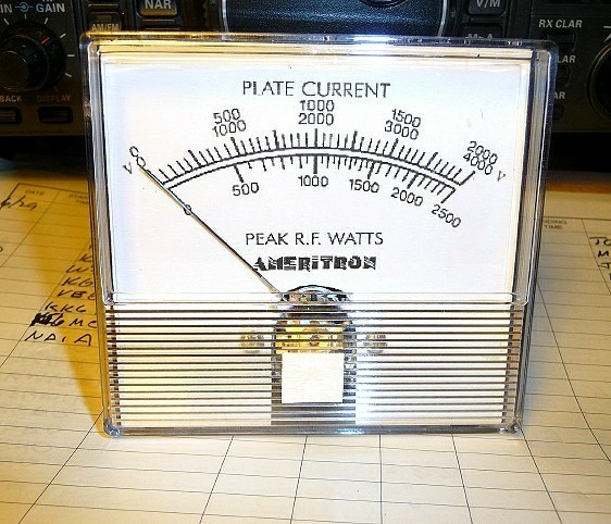 1) IP (Plate Current) range extened by an addtional 1.5 ohm, 3W, 1% resistor in series with R3. This will double the current
range.
1) IP (Plate Current) range extened by an addtional 1.5 ohm, 3W, 1% resistor in series with R3. This will double the current
range.2) PO (Power Output) range recalibrated by adjusting 50K ohm pot. (Incorrect value pot: s/b 10Kohm w/ centering resistors!) 3) HV (High Voltage) range does not need any adjustment; 4000V is OK. 4) ALC range is ok as is. Most all of the required parts are now here and today, 7/17/09, the installation began . . . |
|||||||||||||||||||||||||
|
Installation: In summary, let me say that all of the mods installed and worked as advertised including the EBS-1 mods here . All were installed w/o a problem and worked as predicted or performed as 5Spice analysis predicted. I'm quite pleased! 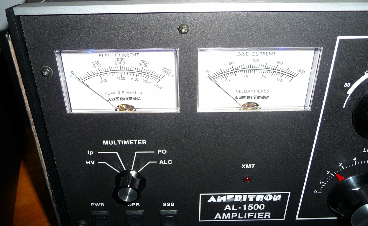 This pic shows the new front panel w/ the replacement Multi-Meter installed [click pic to enlarge]. The homebrew MultiMeter scales have been
expanded as shown. It was very easy to replace when the HV CAP and HV Rectifier boards were removed. It works as predicted when the changes
(described above) were completed.
This pic shows the new front panel w/ the replacement Multi-Meter installed [click pic to enlarge]. The homebrew MultiMeter scales have been
expanded as shown. It was very easy to replace when the HV CAP and HV Rectifier boards were removed. It works as predicted when the changes
(described above) were completed.
|
|||||||||||||||||||||||||
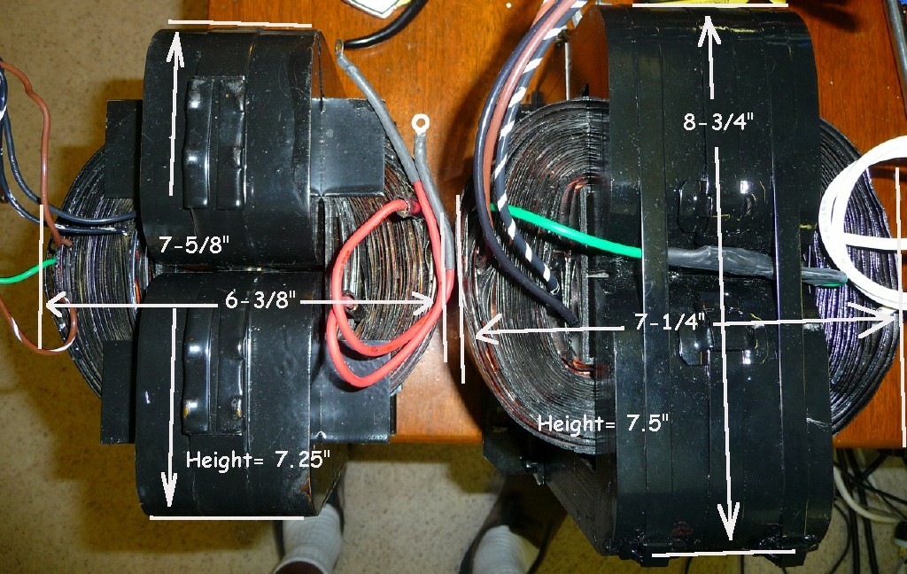 However, the 'bad' news was that new xformer is too big and wouldn't fit inside the box! Jeff is going to see if a special version can be
"wound" that will fit in the space provided. As you see [click pic to enlarge] both the length and width are apx 1" too large and prevent it from
fitting into the alloted space.
However, the 'bad' news was that new xformer is too big and wouldn't fit inside the box! Jeff is going to see if a special version can be
"wound" that will fit in the space provided. As you see [click pic to enlarge] both the length and width are apx 1" too large and prevent it from
fitting into the alloted space. If one can be made to fit, it probably will have only 240Vac input wiring to save "space". So maybe it could have more current output capability. Not sure that this is possible but stay tuned for more info. Now that the new HV Cap Board has been installed, I can use the "220Vac" wiring (boost connection is "green" wire) to obtain a higher plate voltage, 3900 volts @ 240Vac line voltage. The new caps (350uF, 500V) can operate to 4000 volts safely. Dimensions of the available xformer space have been sent and I'm waiting feasibility of a new xformer. |
|||||||||||||||||||||||||
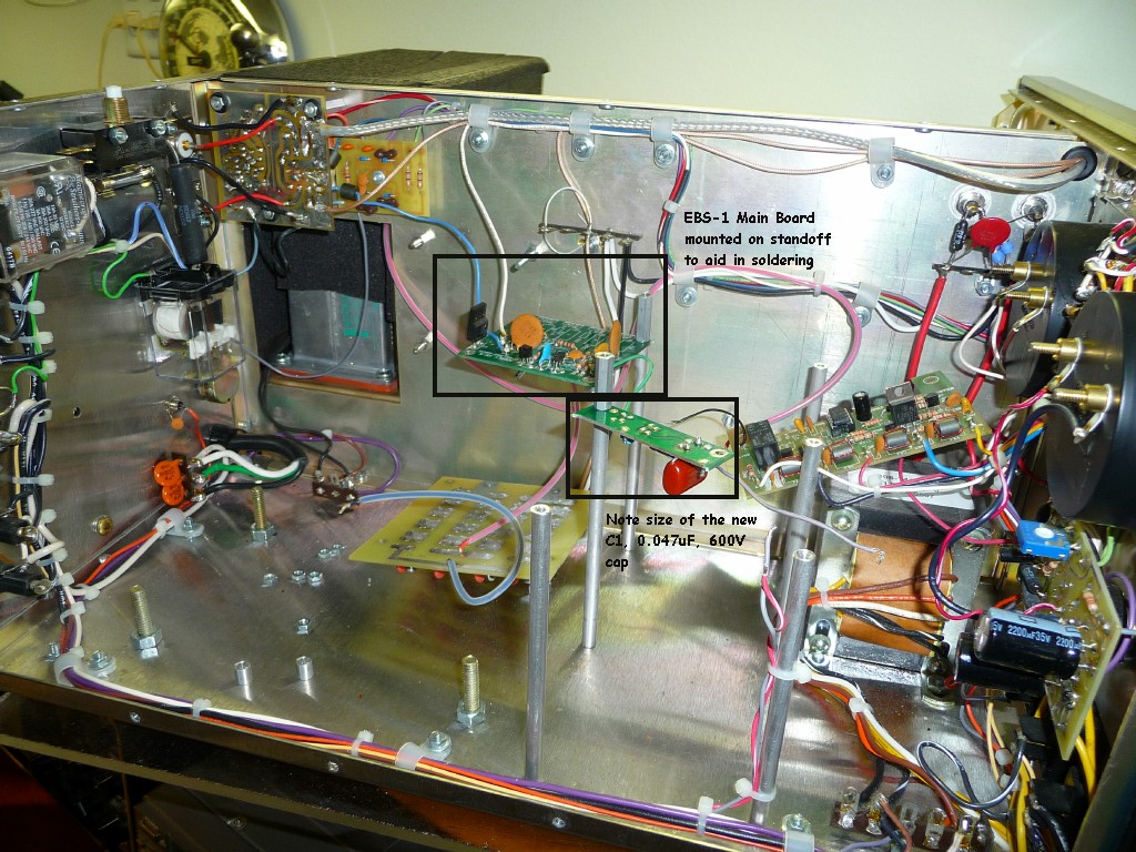 This pic [click pic to enlarge] shows how the mods were made. With the xformer, HV Cap and HV Rectifier Boards removed, you can use the standoffs
as a "work-bench" to hold the ckt boards for soldering. Also the METER Board and M1 (Multimeter) are easily accessed when
these boards are out-of-the-way.
This pic [click pic to enlarge] shows how the mods were made. With the xformer, HV Cap and HV Rectifier Boards removed, you can use the standoffs
as a "work-bench" to hold the ckt boards for soldering. Also the METER Board and M1 (Multimeter) are easily accessed when
these boards are out-of-the-way.Final Conclusions (7/19/09): It appears that a high-power xformer can't be made that will fit in the allotted space without serious "movement" of the HV Cap and HV Rectifier Boards along with removal of the EBS-1 Board. Unfortunately, I do not want to do that since this project was started as a "in-place" modification of existing boards and/or parts to produce a linear w/ more reserve power capability. So now that this is not possible, the AL-1500 will be used with the original P Dahl xformer in the "220Vac" wired mode. The AL-1500 is working as best as it can with the ckt mods and the current xformer wiring. With the line input wiring as shown for the "220Vac" tap, the Linear produces respectible power output with modest drive levels. For example, on 20mtrs, 32 watts input gets 1500 watts output. On 75mtrs, only 30watts is needed for 1500 watts out. I do recommend that you contact Jeff, W8CQ of Harbaugh Electronics for your transformer needs. He worked with me and always was there to answer my questions. The project was a success since the replacement Multimeter, improved METER board functions, dramatic EBS-1 changes and increased operating plate voltage b/c of the new HV Cap Board, have improved the performance of an already fine performing amplifier. |
|
Send me |