
|
K6JRF's Page formerly W6FZC My Mercedes Benz S500 Coupe |
|
Analyze and Troubleshoot "Check Engine" MIL and Electronic Control Units (ECU)!
|
Auxiliary Fans Turn-on Point Modification
Description of Problem |
||||||||||||||||||||||||||||
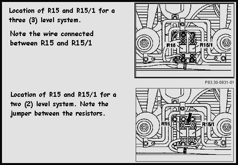 The ckt values of R15 (MB PN: 000 158 37 45) is 0.9 ohms and R15/1 (MB PN: 000 158 39 45) is 0.6 ohms. The in-ckt values are smaller and are shown in the schematic. The mounting points for R15 and R15/1 are shown in the drawing below. Both resistors are stacked vertically in the newer models but for my car, they are horizontally mounted end-to-end. The fans can be activated by either temperature or refrigerant pressure. According to MB data, here's the as-delivered Temperature and Refrigerant pressure vs stage activation: |
||||||||||||||||||||||||||||
|
The fans can be switched on by either high temperature (over 100 deg C) or by high refrigerant pressure (over 14 bar or 206 lbs). This modification concentrates on the 'temperature' side so that the fans may be activated when a certain temperature has occurred and does NOT require that the A/C be in use. The fans use the Coolant Temperature Sensor [CTS] (NOT the ECT sensor (B11/2)) and turn on when the resistance of the CTS [PN 008 542 45 17] is as shown above. Note that to TEST the fans cut-in, 310 and 250 ohms are substituted for the actual CTS (per MB Maintenance Manual). This means that at 100 deg C, the resistance of the CTS is 310 ohms; at 107 deg C, it's 250 ohms. Thus to 'fool' the system, you need to add a resistor in parallel to the CTS to make it look as though the temperature is higher than it really is! Resistors in parallel LOWER the resistance value. What temperature to use? I think it should be between 90 and 95 deg C, with 92 deg C being my choice. That's simple enough. But of course, you need a sturdy mechanical package to 'house' the resistor. After trying a few things, I made a choice. If you came here front my home page, you already know how I packaged it!. If not read on. Resistor Value: Use a 1%, 1/4 watt FILM type resistor to ensure stability. For example, Radio Shack PN RSU 11345741 (1.1K). This is NOT an in-stock part, so don't try to get one unless you special order it. There are numerous other sources for this type/value resistor, typically any electronic's parts house. A CARBON type should be avoided since they will drift badly with heat. So what is the value to use? 98 deg C ====> 1780 ohms 95 deg C ====> 1200 ohms 92 deg C ====> 1100 ohms ==> preferred value! Note that the higher you choose to have the AF kick-in, the larger the value of resistor that's needed. That's because the sensor value changes exponentially near 100 deg C. The resistor should be "electrically" across the two (2) leads to the CTS sensor (B10/8). A value that is in between the stated values will move the point accordingly although it will be hardly noticeable. Doing the Modification My picture shows how I did it. Locate the A/C CT sensor (B10/8) and disconnect it. Using a small blade screwdriver, take the connector apart and solder the resistor (1.1K ohm) into the pin leads where the wires go as shown below. Then snap the top back on, and plug it in. That's all there is to it! 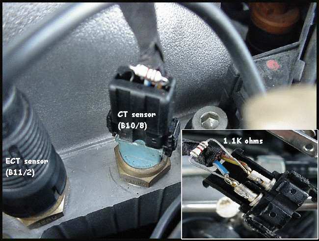 Testing shows that it turns on at 92-95 degs C instead of 105 deg C as before. Used the instrument panel gauge for the
measurement. After coming on, it takes the temperature down to about 88 degs and then shuts off. With A/C on full, the
temperature stays below 98 deg C, as measured on a 82 deg F day, doing city stop-go driving.
Testing shows that it turns on at 92-95 degs C instead of 105 deg C as before. Used the instrument panel gauge for the
measurement. After coming on, it takes the temperature down to about 88 degs and then shuts off. With A/C on full, the
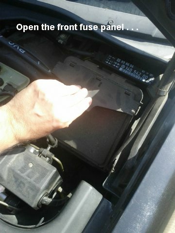
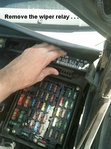
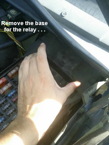
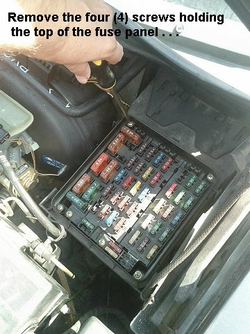
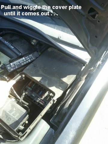
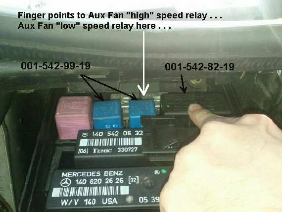
temperature stays below 98 deg C, as measured on a 82 deg F day, doing city stop-go driving. Remember that this change involves a system with TWO (2) coolant temperature sensors where the power train management is done via the ECT sensor and the A/C and auxiliary fans use the CTS sensor (ie a separate sensor). If NOT, this change will not work because the ECT sensor is used for fuel and ignition mapping. Changing the temperature will also change the mapping by 'some' amount. This modification is also FAIL SAFE. If the resistor were to fail, which is OPEN, then the fan ckt will revert to 'stock' operation. If you do not feel as though you can not do this yourself, a complete package is available for you to simply plug-in. It's called Cool Harness(c). See more details on the main page. CLICK HERE for pricing. Don't forget Purple Ice (PI): You can now (for summer driving) add PI to a 60/40% mixture of water/antifreeze. This with the CTS mod will keep your car's temperature gauge well below where it used to be! Hope that you find it useful. Aux Fan Relays Location There are many things that can cause the A/F to not work. Chief among these is the wiring becoming brittle and failing. Also the dropping resistors burn out causing an "open" to the system. Some time the A/F "high" and "low" speed relays fail or become "ohmic" and cause intermittent operation. Both relays are tucked away behind the car's fuse panel and are somewhat difficult to find. The following pictoral by Benzworld's "slowhands" makes it very easy to replace and/or swap the relays to t/s the problem.
|
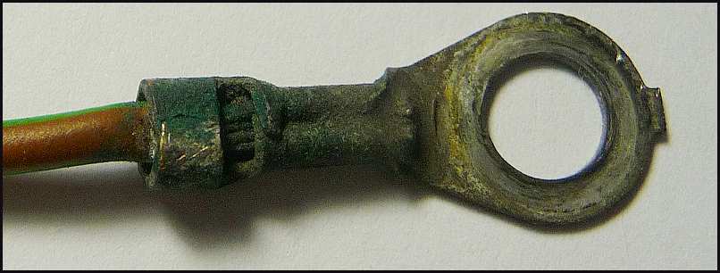 For those who don't want to read the thread . . . here's what caused the problem.
|
Send me |