 I like the shades! |
K6JRF's Page
formerly W6FZC Yaesu FT2000 ESSB Audio Setup |
 |
(Updated: Nov 14, 2020)
- - What's NEW - -
[12/19/20] - AL-1500/AL-82 Blower Upgrade . . . click here
[11/14/20] - Remembering John, ON4UN and Frida . . . click here
[10/30/20] - Adding a Keypad to the Guardian GDO . . . click here
[08/17/20] - FM-DX Tuner and FM Yagi Design - 4el new yagi design. . . click here
[04/15/20] - FTdx101D 'ttbf' Spice Ckt Analysis and How to Enable . . . click here
[03/21/19] - Use "UrbanBeam" Concept to Design a compact 3el 20M Yagi. . . click here
- - Click here for the Main Menu System- -
|
Instead of some cheesy SuperBass function, controls are very simple: Power, Presence and Volume. Presence is basically Tone: more treble or bass in one knob. All the controls are on the right speaker, and the setup is integrated: no additional amplifiers are needed, just the supply and the two cabinets. 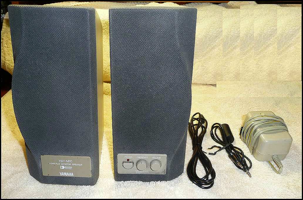 Most
importantly, the M10 supports both line level
and headphone level input. There is an input for
power, supplied with a "wall-wart" type power
supply which unfortunately takes up an extra
plug space. There's an output on the right
speaker to power the left speaker along with a
stereo input. The signal connectors are both
1/8" stereo mini-jacks. Click
to enlarge the picture Most
importantly, the M10 supports both line level
and headphone level input. There is an input for
power, supplied with a "wall-wart" type power
supply which unfortunately takes up an extra
plug space. There's an output on the right
speaker to power the left speaker along with a
stereo input. The signal connectors are both
1/8" stereo mini-jacks. Click
to enlarge the pictureMy first test of the YST-M10 was to on my desktop computer which I still use! Turning the volume up high, the first brass horn blasts of a Stan Kenton big-band scared me! I've used these for speakers for a long time and the sound quality fills the entire room today as it did when first tried. When I need volume, the M10 delivers! It has great range, and you can never hear the thing resonate. The disturbing thing is that the M10 is only rated at 10W. It uses Active Servo Technology, which, according to a more knowledgeable friend, basically improves the SPL and quality by actively monitoring the output and changing the speaker signal dynamically. It compares to 80W PC generic soundcard speakers. Comes with a two (2) 1/8" mini stereo cables and 19V power supply. Just hook up and enjoy! Price was $50, now reduced to $30 payment to my Paypal account, shipping is extra. |
|
The OWA explanation: The Optimized Wideband Antenna (OWA) is antenna feed-point matching method developed by WA3FET that provides an increased feed point impedance while widening the VSWR bandwidth. The OWA is implemented in a yagi by moving the first director very close in front of the driven element. The only negative aspect of OWA yagis is that they give up a slight amount of forward gain (typically less than .5dB) from a conventional yagi. This small degradation is impossible to notice in operation and is well worth the simplicity of direct feed and the excellent bandwidth. Analyzing the "OWA" method; O = optimized . . . this word causes difficulties; optimized means only ONE parameter is "peaked", not all! W = wideband . . . implies complete band operation. Nothing wrong with that; A = antenna . . . dipole, yagi, quad, etc. No problem here. So the use of the term "optimized" is a problem! What does "OWA" method actually accomplish . . by moving the director closer to the driven element, the feed-point impedance is raised which reduces the F/G and reduces the SWR thereby increasing the operating bandwidth. That, friends as stated, is a "method" or a "technique" and results state that this method will make an optimized wideband antenna. The problem is that the optimization process only peaks ONE parameter at the expense of the others. The word "optimize" by definition means to make as perfect, effective, or functional as possible. Does performing the OWA method result in the best F/G and the best F/B and the best BW? The answer is NO! Performing this "method" results in a peaking of one parameter and compromise for the remaining parameters. This is far from the BEST, most favorable, ideal or perfect. So the OWA method can't be the BEST for all parameters! If I happen to want more F/G, the OWA method will not provide that. So performing the "OWA" method does NOT result in the BEST that can be done. However, the authors use the term optimize which implies to the reader that the antenna is now the best it can be when actually, it is less than it was before! Here's an example - - the HG204BA yagi features four (4) elements on a 26ft boom. The 'graphical' summary on the left shows what it does "out-of-the-box". Next to it on the right is the OWA technique to transform the yagi.   |
| The stock 204BA meets a lot of users needs;
good F/G, good F/B ratio with reasonable SWR
across the complete 20M band. Could that be
called "the best"? If any version of this yagi
could be called the best, this is it! There is
absolutely NOTHING wrong w/ that yagi as is. For
MOST Hams, this yagi provides the overall best in F/G, F/B
and SWR that can be had for that boom
length. And you certainly
can operate over the full 20M band w/o any SWR
problems! By applying the OWA method/technique, the antenna is modified to loose some F/G while lowering the overall SWR (1.5:1 vs 1.2:1 is nothing to write home about). The main difference is that you can now use a direct 50 ohm coax feed. That is not necessarily an advantage b/c a balun is still required as it was before the OWA method. The only thing that has changed is the possible elimination of the "match" (hairpin for the HG204BA). Is this yagi now "better" than stock HG204BA? I don't think so! Actually the yagi's specs have been degraded but now some can now call this an OWA. A change s/b made to the "name"* to better define what was done to modify the antenna and remove the ambiguity using the word "optimized". This removes the mis-understanding with most Hams who think the antenna is now the "best" it can be b/c it was "optimized"!!! * A more appropriate term is . . . . Comprehensive Wideband Matching - CWM . . this much better describes what's going on. You loose F/G for the sake of operating bandwidth by changing feed-point impedance as the result of moving the director closer to the driven element. The resulting antenna is not OPTIMIZED for all parameters. |
|
FBN-83 (1400ma) to FBN-94 (1800ma) 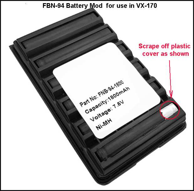 If you purchase a replacement battery for the VX-170 2M HT and choose the FBN-94 to replace the FBN-83, you need to cut off the plastic battery cover from the bottom right corner as shown so that the battery's ground shows (metal case). If you don't it won't CHARGE when you plug it into the standard charger via the "Ext DC" side input. |
|
Received email from Damon, KJ7E regarding the latest FW update: 202003 of 3/16/20. Here's what he wrote: 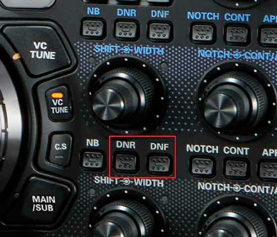 Been a long
time, lots to talk about, but I picked up
an FTDX101MP a few months ago and just
figured out how to enable the TTBF for
extended TX bandwidth. With the latest 202003
firmware update package you can enable the
TTBF TX BPF option.
Same as the FTDX5000, power on and press
DNR+DNF buttons on the main RX
side (lower set).
Been a long
time, lots to talk about, but I picked up
an FTDX101MP a few months ago and just
figured out how to enable the TTBF for
extended TX bandwidth. With the latest 202003
firmware update package you can enable the
TTBF TX BPF option.
Same as the FTDX5000, power on and press
DNR+DNF buttons on the main RX
side (lower set).Did a real quick sweep between the two settings this morning, didn�t plot it but here are the results; [Also received an email from Terry W6RU and he confirms the addition of the 'ttbf' mode by following the above instructions. Charles, W4CO has also reported that performing the FW update does indeed give the ttbf mode on his FTdx101MP.] |
|
= FTdx1200 & FTdx3000 4Khz SSB TX = Two things show that this is possible: 1) The "WIDTH" control can be extended to 4Khz by turning it fully CW; 2) The specs for Menu #104 (for both radios) state that these TX BW are possible: [1-30= 100-3000]; [1-29= 100-2900]; [2-28= 200-2800]; [3-27= 300-2700]; [4-26= 400-2600] and 3000WB. The last setting "3000WB" [100-3000] is found on the FT2000, FTdx5000, FTdx9000 radios; when the "magic" two buttons are pressed while pressing the POWER switch, "3000WB" is replaced in Menu #104 by "ttbf" which is the 4Khz TX mode. The two buttons for the FT2000 are described in the FT2000 table below.  Received an email tonight from VE3WCQ which stated . . . " I thought I would let you be the second site to learn of the TTBF for the FTdx3000 and FTdx1200. 1. Make sure power is off. 2. Find the CS and TXW buttons just left of the Freq Dial. 3. Push and hold "CS" and "TXW" buttons in while powering the radio via the "ON/OFF" switch. 4. Select Menu# 104 and see that "TTBF" has replaced 3000WB. 5. If you wish to go back to 3000WB just do steps 1 to 4. Well that's it. I hope your followers will enjoy. Mike VE3WCQ " Tnx Mike for the info . . many owners will have a big smile after tonight! Yaesu used a great choice of buttons; the "C.S" is direct MENU access-select while the "TXW" selects the SSB TX BW. For EQ and processing selections visit my "4Khz SSB EQ" page here For a "quickie" EQ, try these settings for the parametric EQ mode (#159 to #167) with a 'quality' mic plugged directly into the front panel connector; ----- Desc ----- Menu# -- Setting-- PrmEQ1Freq ----- 159 ---- 300 PrmEQ1Levl ----- 160 ---- -6 PrmEQ1BW ------ 161 ----- 1 PrmEQ2Freq ----- 162 ---- 700 PrmEQ2Levl ----- 163 ---- -5 PrmEQ2BW ------ 164 ----- 1 PrmEQ3Freq ----- 165 ---- 3200 PrmEQ3Levl ----- 166 ---- 10 PrmEQ3BW ------ 167 ----- 1 I've added the FTdx3000 to the "NO EQ" page here. OK, how about some other EQ entries? |
|
The FTdx9000 and FT2000 can be programmed to a 4Khz SSB Tx BW, so should the FTdx5000. That's what I've always believed and sure enough, it can! NAIA was the first to discover this as I recall. It's easy to do and here's how to get the radio into the 4Khz SSB TX mode. So how is it done? Access Menu #104 and look at all of the entries. One of them is labeled "1-30" and another "3000WB". "WB" stands for "Wide Band". As you read in the "How to EQ . . " section, both are identical. So the "dual" entry implies that the "WB" can be made to extend further. And it can! 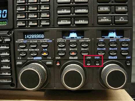 How? Simply do
the following; How? Simply do
the following;
The picture shows the two (2) pushbuttons . . . The radio will turn on normally except that when you access the "Tx BW" menu #104, you'll see that the "3000WB" has been replaced with "TTBF". So now, "1-30" is still the same, 50hz to 3Khz but the newly added "TTBF" has 50hz to 4Khz Tx BW. The SSB Rx BW is still 40hz to 4Khz. You can return the radio to 3Khz SSB BW by repeating the same steps at turn on. Very simple! |
|
The FTdx9000 and FTdx5000 can be programmed to a 4Khz SSB Tx BW, so should the FT2000. That's what I've always believed and sure enough, it can! Yours truly was the FIRST to find the magic buttons even though others posted (K3UR, KC4PE and others) as if they found it. So how is it done? Access Menu #85 and look at all of the entries. One of them is labeled "1-30" and another "3000" or "3000WB". "WB" stands for "Wide Band". As you read in the "How to EQ . . " section, both are identical. So the "dual" entry implies that the "WB" can be made to extend further. And it can! How? Simply do the following; 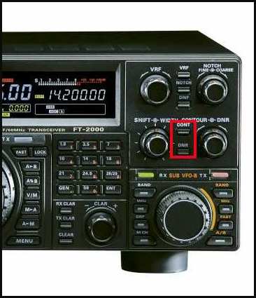 The picture
shows the two (2) pushbuttons . . . The picture
shows the two (2) pushbuttons . . . The radio will turn on normally except that when you access the "Tx BW" menu #085, you'll see that the "3000WB" has been replaced with "TTBF". So now, "1-30" is still the same, 50hz to 3Khz but the newly added "TTBF" has 50hz to 4Khz Tx BW. The SSB Rx BW is still 40hz to 4Khz. You can return the radio to 3Khz SSB BW by repeating the same steps at turn on. Very simple! Unfortunately, the EQ schemes that I've developed for the "3Khz" Tx BW need to be augmented to take advantage of the increased 4Khz SSB BW. I've added a new section to compliment the 3Khz EQ section called "How to EQ the FT2000 - 4Khz Tx BW". Click here to see my current audio rack settings. The old section was renamed to "How to EQ the FT2000 - 3Khz Tx BW". The new TTBF EQ section will build as time progresses. The MP3 clip below demonstrates the fuller 4Khz SSB audio captured by Duke, NA1A on a Flex5000A @ 4Khz BW. The extra BW, results in a more "relaxed" and "open" sound. This clip shows that fullness can also be had at the same time! |
|
Recently Hans, PA1HR created a summary of the QST reviews of modern day radios. These include Flex6600A, Elecraft K3, varios Icom radios and the Yaesu line including FTdx9000, FTdx5000, FT2000 and FT950 to name the more popular radios. This update shows the new FTdx101D Be prepared for a <<SHOCK>>, the FTdx5000's rcvr is a brick-wall of 114db! Even the SSB transmitter's 3rd Order IMD specs are apx 10db better than the next closest radio!!! And the newly released FTdx101D is now ranked "2nd" but if you look carefully, it could be #1 depending on how you sort/rank the data! The format of the report is "landscape" in order to better fit the large amount of data for each item. It also has a "Power Amplifier" section to review and rank the many HF linear amps available going back to 1997. New addtion for this month: Flex 6600M. Click here to download this latest version. Here's the "Sherwood" report: Click here to see the ranking report. The top radio today is the FTdx101D . . . and the FTdx5000 is ranked 12th based on the criteria. My old FT-2000D is ranked . . . 124th!!! It's a wonder I can hear anything??? |
|
The information here centers the use of external audio equipment and, secondarily, use of the internal parametric EQ to attain improved Tx ESSB audio. The techniques described here are directly applicable to the FT2000, however the recommendations are applicable to any modern HF transceiver. The capabilities of this radio seem, at first, overwhelming. But once you spend some time looking at the operational manuals, browsing through the schematics and playing with the knobs, you see the best of all worlds is built into this radio. The "Technical Supplement Menu" section contains the "service" documentation for the FT2000 and DMU module. Each PDF contains the schematics, board layout and parts-list of all modules. This data is a must if you plan on making any changes. Also, the "Alignment" manual contains the "how-to-do" instructions including the required test equipment to properly align the radio. Please RIGHT-CLICK and select "Save Target As" to download the PDF files. The main Service Manual is 25Mb! The Owners Manual's internals can be copied and/or extracted to other programs.
In the "Audio Techniques Menu" section, specific instructions for attaining 'good' ESSB audio including adjustment techniques, alignment improvements as well as tips for proper audio system interconnection. Included are links to equipment manufacturers. These techniques are applicable to any radio however they are tailored for the FT2000.
In the "FT2000 Modification/Alignment/Repair Menu" section, improvements to the FT2000's circuits are shown. Mose "Mods" are shown in detail using Spice ckt analysis to show the actual performance of the "stock" ckt as compared to the improved operation after the mods are made. In addition, all of the details of required parts along with instructions that show how-to-accomplish the changes including the PWB parts layout from the Service Manual. Presently, there are technical analysis of the FT2000's VOX and MIC ckts. In the "Repair" section, the failure of a front panel pushbutton (PB) is explained and the repair steps are shown in words and pictures.
In the "Amplifier Modification Menu " improvements to accessory equipment such as linear amps, etc are detailed. This section concentrates on using Spice ckt analysis to show the actual performance of the "stock" ckt as compared to the improved operation after the mod(s) are made. In addition, all of the details of required parts along with instructions that show how-to-accomplish the changes including the PWB parts layout from parts suppliers such as Mouser Electronics. Presently, there are a technical analysis of the AL-1500, AL-572 and 6mtr mod to the SB-230.
In the "Antenna Design Techniques Menu " standard methodology for using available antenna design sw to successfully design any type of antenna desired such as "wire", "vertical", "yagis", and "quads" to name a few. The first section concentrates on detailing the necessary design techniques for using Yagi Optimizer [YO], Antenna Optimizer [AO] and Terrain Analyzer [TA]. This design SW was developed and perfected by Brian Beezley, K6STI.
In the "General Interest Pics" section, improvements to my home and surrounding area is detailed. Recently "Operation No-Grass", "Solar System Update" and "Bird Spike Repair" were completed with pictures showing the highlights of each project.
|
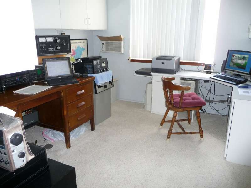
| This room was remodelled
recently and the goals were to make it clean, comfortable,
well lighted and organized, all
of the things that the former studio was
not! Also made sure to have lots
of 120 Vac outlets. To that end,
a new service line was added which makes
36 outlets available! The
studio is also wired for 240Vac which
powers all radios (FT2000D + TS-711) and
AL-1500 linear and Y0-301 scope. I
recommended doing this b/c it isolates
the high current draw devices and
improves the power transfer efficiency.
The air conditioner was recently replaced w/ a new LG 8500BTU unit. A/C makes radio operation a pleasure on hot summer days. The computer system has been 'upgraded' w/ a new monitor, keyboard, printer and scanner shown in the picture below. |
 |
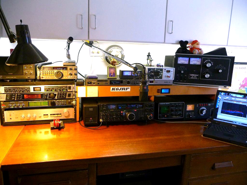 |
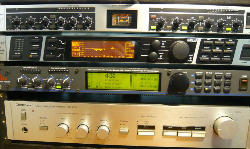
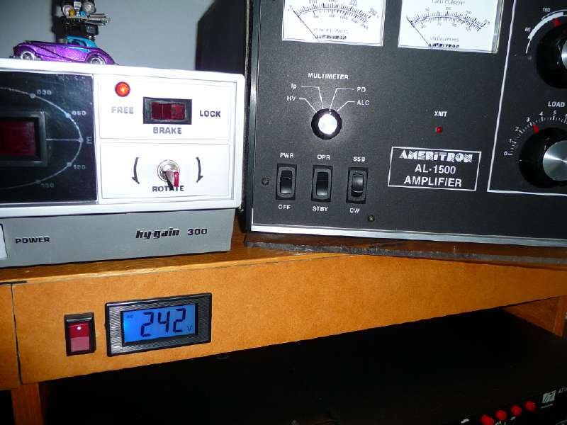
The desk lineup shows; audio
rack with three (3) studio grade audio
processors plus a Technics 40W audio
amplifier w/ equalizer, Yaesu FT2000D,
Yaesu YO-301 monitor scope, Palstar
AT-1500DT tuner. In front of the audio
rack is a Dell C640 P4-2.4Ghz laptop
used for digital recordings/playback,
5Spice analysis and making/recording
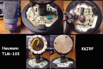
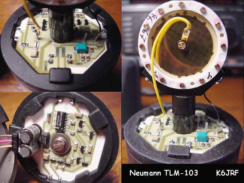
Spectra Plus charts. Second tier shows; SP-5 Speaker w/ Time Wave DSP, TS-711 2M all-mode Transceiver, Sony E10 Minidisc recorder, Nye-Viking wattmeter, HyGain HDR300 rotator and Ameritron AL-1500 linear amplifier. The microphone is a Neumann TLM-103 Anniversary issue which has been my main (and only) mic for many years now! When you have one of the most faithful sound reproducing mics in the world, you don't need to experiment. |
Sony MDS-E10
mini-disk recorder. Makes flat recordings
from 20hz to 20Khz. Note: fix "eject"
problem: uxcell Nitrile Rubber O-Rings, 17mm
ID x 1mm dia.
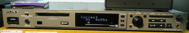 click here for a larger picture |
FT2000D w/
external switching PS.  |
|
My current audio
equipment. Starting from the top; 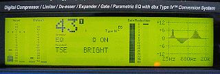 The DDP equalizer screen with its 'visual' frequency display! |
Tower and Antennas
 The current antennas are different from my
previous shown
here.
The current antennas are different from my
previous shown
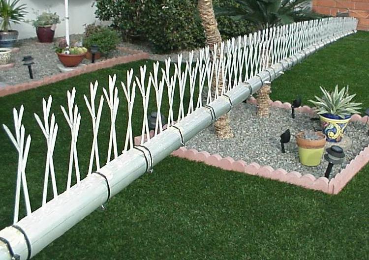
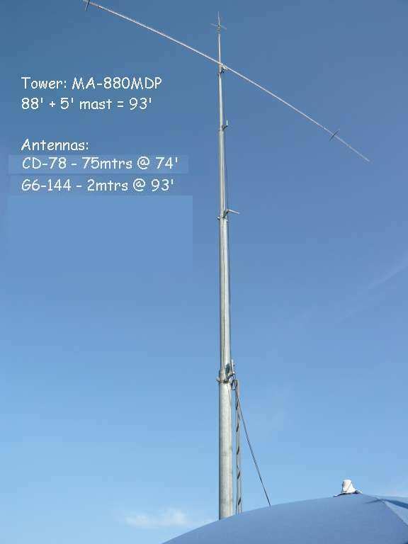
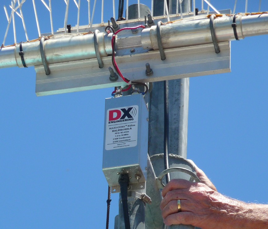
here. The large 20mtr mono-band antenna spread out over the deck and pool as the picture shows and it provided a "resting-place" for all birds to constantly 'bomb' the real estate below. After 35+ years, they won so all of the antennas were removed.  It's been over 8 years and all traces of birds and their droppings are gone. So I've put up a different, mostly smaller, antennas and these have Bird Spikes added to the elements and boom. This product prevents birds from landing and there is no mess to clean up on the deck or in the pool! My current plans include putting up a LJ-203BA, a 3el 20mtr monoband yagi and a Create Design, CD78 75/80 dipole. On top of the tower is a Hustler G6-144B 6dB colinear antenna, all with Bird Spikes mounted on all potential bird-landing surfaces! The picture shows George, W6ZZ [sk 11/15/14 - rest in peace], Terry, N6CW and yours truly along w/ our respective ages. The "Old Amigos" continue to ride! The alternate picture shows a closeup of the CD78 feed point taken by my "hand held" Panasonic DMC-TZ5 camera on the ground at 17x zoom! Amazing Optical Stabilization; even the label on the DX Eng balun is clearly readable. CD78 Dipole Analysis The CD78 is an amazing antenna for it's size. The 75 mtr gain is lower than a full size dipole b/c of its reduced size, apx 58 ft from tip to tip but since it can be mounted high on a tower, the height makes it very efficient b/c of the lowered radiation angle. It also loads on 20mtrs perfectly. I've used it on 15mtrs w/ the FT2000's automatic tuner. Using antenna software called Antenna Optimizer [AO] by K6STI, Brian Beezley, I checked to see what it would take to increase the gain. AO was able to quantify the gain loss due to the dipole's "coils" and then show what can be attained with lower loss coils. Click here to see the AO analysis results. |
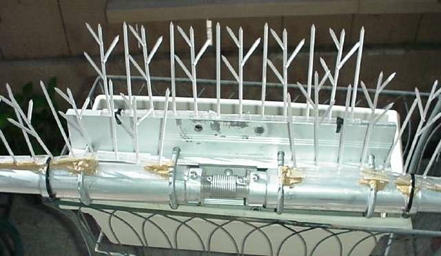 click for CD78 closeup w/ Bird Spikes  click for overall tower picture click for closeup of CD78 mounting After 41 years of studying birds, I've found the "secret"; if you wish to be bird free, you MUST not let them land. If you do, you WILL have a bird problem. It's as simple as that! 5/13/11 Oh, Oh, there's bird poop on the deck and in the pool . . . . click here to see why |
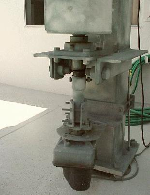 |
The tower is a 13 year old
crank-up tubular tower by US
Tower MA-850MDP. This base
system, MARB-850 rotator base, is
planted in 6' x 6' x 4.5' of reenforced
concrete and is bolted to the concrete
via the four (4) 2 inch diameter bolts.
Besides holding the tower, this allows
for easy leveling of the overall
structure. Also the base allows the
tower to fold over when it's fully
collapsed via the two 2.5 inch triple
hardened bolts used as hinges! The five (5) section tower sits on a trust bearing supplied with grease fittings in order to keep rotational wear to a minimum. The bottom plate supports most popular rotators. I've used the HyGain HDR-300 rotator (5000in/lbs of rotating torque) for 13 years with no problems. |
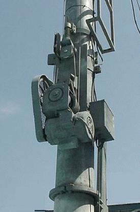
| The tower system was purchased
with the positive pull-down feature.
This feature is very desirable during
high winds. If you've gone though this,
then you know what I mean! The reversible 1/2hp motor mounts a 1' pulley driving about 10:1 reduction gear that powers the worm drive box with another 40:1 internal reduction. With all this power, it breaks tangled coax (or anything else) without hesitation! Unfortunately this has happened at least once! The upper spring and pulley assembly takes up slack in the positive pull-down cable that goes directly to a tie point on top of the tower. The tower is controlled by two (2) limit switches that set the highest and lowest points before the motor power is cut off. The control box is basically a junction box for 120Vac and contains reversing and limit switch wiring. The ladder allows you to climb the first section (20') when it's fully collapsed. |
 |
|
This new HF amplifier is just
great addition to my studio. The
Ameritron AL-1500 uses a
single 8877 (3CX1500A7) tube from Eimac
and it outputs 1500W for 40 watts drive.
The amp has an Electronic Bias Ckt
(EBS-1) which cuts the tubes off very
cleanly between words. Thus the total
dissipation is kept remarkably low and,
even more important, the heat buildup is
minimized. Check here to
see how it was mounted into a tight
space. This is my main amplifier. |
| I never thought that I'd never
sell this amp but you can't ever say
"never"! I don't use it so, it was sold
to Jerry, W6XI and the pic shows
that it's headed for a new home in
Arizona. The amp is 35+ years old and
it's never 'failed' or even hiccuped!
Jerry will enjoy this amp from now on .
. I sold it to him if he guaranteed that
he wouldn't beat me in the pileups . . .
|
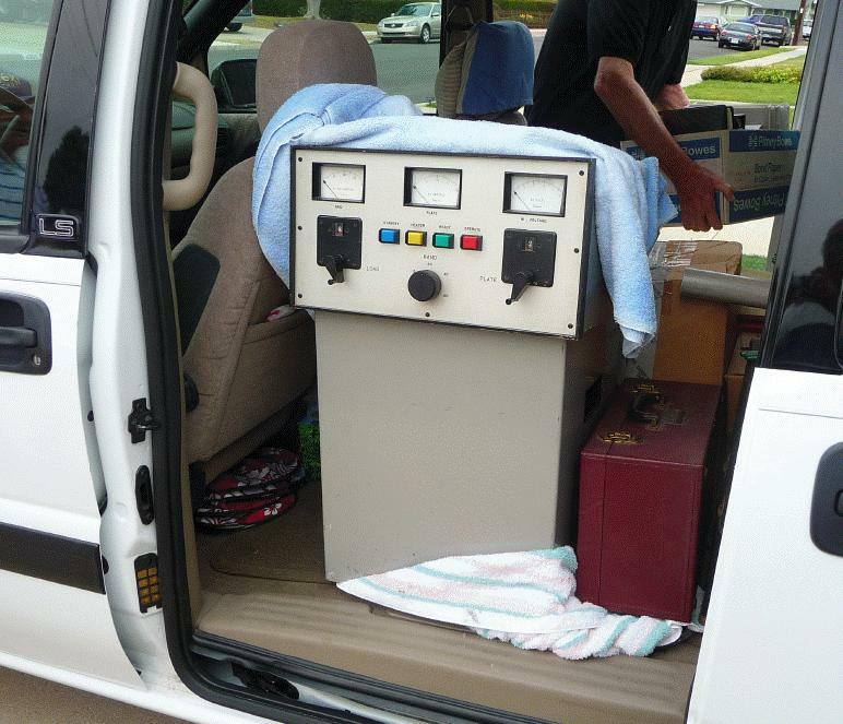 click for larger picture |
| Detailed
Audio Rack View: The Behringer MIC2200 preamp has a combination tube and solid state amplifier that gives the best of both worlds. A tube preamp in general gives a warmer sound to the audio from the mic. The Behringer Ultra Curve Pro DEQ2496 is a unique audio dynamics processor that employs 24-bit A/D/A converters in a 96Khz sampling environment. The DDP is a unique audio dynamics processor that employs 24-bit A-D and D-A converters under control of a dBx developed DSP chip with a LCD display. A truly marvellous dynamics unit in one increment of panel height. |
|
 click for detailed picture |
The key
element in audio work is the microphone
and there are as many opinions as there
are microphones, so here we all tend to
get subjective. The best overall mic is
probably a 'dynamic' such as the
Electrovoice RE20
or Shure KSM44.
These mics produce audio with little or
no coloration. I personally have settled on the 'condenser' style mic because of its high sensitivity (typically 15db more sensitive than a dynamic), and broad pickup pattern. Currently I'm using the Neumann TLM-103. It's a great example of a well engineered and quality manufactured product albeit pricey! The Marshall MXL2003 is a good condenser microphone that is reasonably priced. For those who don't want to spend a lot, try the Shure C606 dynamic mic. Priced around $25 and it's can be used directly (XLR connection) into the FT2000 or FT950 using the internal EQs with a 75hz to 12Khz response and a rise starting at 1Khz. Marvellous mic for the price. |
| W2ONV became a SK on Aug 12,
2007 due to a battle with scleroderma. His
disease became aggressive and quickly caused
other immune diseases resulting in the
taking of his life. A sad day for all Ham
Radio. Bill had been "one- two, one- two" for so many years before anybody took notice that many incorrectly attribute his SSB experiments to the early 90s. In truth, he had been doing that in the late 80s and, in fact, I would "stop-by" 14.178 and ask if he got it "right" yet. He'd reply that when he got to "three" he would be close! I asked why he was wasting so much time with this "hifi" audio. One of my problems, was simply that I couldn't hear it b/c of a "standard" rcvr bw of 400hz to 2400hz. His radio transmitted 50hz to 3.5Khz, so that's why it was a mystery to me! The Spectra Plus chart captures the essence of Bill's SSB audio.  About a 6 - 7 months later, the new FT1000D ESSB radio was born. The radio continued to evolve for another year as more advanced mods were done. The details of how this was done are on my FT1000 web pages here . Suffice to say, that this delighted Bill to no end. He would mention it every time he found me on frequency. He was so proud that it was done and a member of the 'group' did it. That's the kind of man he was. I left active ham radio in 2000 or so and was off-the-air until about 6 months ago. I removed all of my antennas so I couldn't get on the air even if I wanted . . . and believe me, I wanted, mainly to talk to Bill. As I was 'getting' ready to come back, I was told of his passing. All I can say, it was as if my father had passed. It delayed me for at least, another 6 - 8 months before I got over his demise. When I was setting up the "external audio rack", Bill said that he had the 'magic' setup info that will give you great audio. At that time, I was naive enough to believe him so he said he'd send me the proven Aphex setup info.  Here's the sketch of Bill's setup (click for
larger view) that he used when he ran Aphex
audio processing. It was well marked meaning
it had made the 'rounds'. The "key" was the
Aphex "Big Bottom" setup outlined in the
blue box. The BB drive . . . "must be
exact"! Nothing against Aphex (and
Behringer, etc) but the BB circuit was a
'joke' . . The only thing that's a 'secret'
is the fact that all audio is mainly
dependent on the 'voice' and mic driving the
rack. However, I treasure that info and have
shared with you all today.
Here's the sketch of Bill's setup (click for
larger view) that he used when he ran Aphex
audio processing. It was well marked meaning
it had made the 'rounds'. The "key" was the
Aphex "Big Bottom" setup outlined in the
blue box. The BB drive . . . "must be
exact"! Nothing against Aphex (and
Behringer, etc) but the BB circuit was a
'joke' . . The only thing that's a 'secret'
is the fact that all audio is mainly
dependent on the 'voice' and mic driving the
rack. However, I treasure that info and have
shared with you all today. |
Speaking of
knobs, I'm not much for marrying a computer
w/ a radio b/c I'm basically an old-timer
and I still love buttons, knobs and sliders
on the radio. Well, last night, I
decided to try a Software Defined Radio
(SDR) program so I d/l the latest version of
Ham Radio Deluxe (HRD), V4.0 SP4
build 1901 and installed it. The work that
has gone into the development of this fine
program is to be lauded. Simon Brown,
HB9DRV has done fantastic work to
bring the program to this latest state of
perfection.  I works so well that I couldn't believe what
I saw. All functions work so nicely and
effortlessly, that I was taken back. All of
the buttons and knobs on the radio are
available in HRD they all work as
advertised.
I works so well that I couldn't believe what
I saw. All functions work so nicely and
effortlessly, that I was taken back. All of
the buttons and knobs on the radio are
available in HRD they all work as
advertised. The picture shows the basic FT2000 radio setup (sliders are not shown). You can either click a button on the screen w/ your mouse or use the radio. The program has many features and one of these is the "DX Cluster" announcements right on your screen sorted by band. If you're interested in a particular station, you simply "click" on the station and your radio changes to that frequency and aims the antenna. It takes the "work" out of chasing DX. The program can be downloaded here. Scroll down to the "Installation" section and click on the highlighted "Download". After the d/l completes, click on the main file EXE program to start the installation. |
|
Three versions of an excellent HAM Timer program by WC0EM is located here Ham Timer V3.0 is available for Windows Vista, 7, 8 and 10; 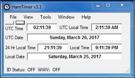 Ham Timer V2.31 with re-sizeable windows for Windows XP; 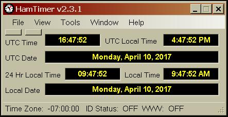 Ham Timer V1.22 is available for ALL Windows. 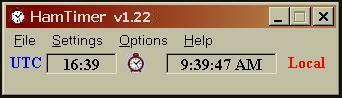 Bj�rn Vangstein, LA5MDA FT-2000 Audio settings here. Checkout W3YY info page for FT-2000 here for early overall review. MARS/CAP mod for FT-2000 here. Mods.dk compilation for FT2000 here. The DXZone for FT-2000 resources here. Larry, W3OZ, ESSB audio info and other neat things here. Send me Visitors since July 3, 2000 |